
Operating instructions


28
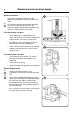
Låsenhet
Låsvred
Låsarm
D1
Control unit
The control panel (1), mounted at the front, includes all components necessary for oper-
ating the machine, such as display window, control switches and a key-operated switch.
The printed circuit board with the microprocessor electronic timer is mounted just behind
the control panel.
B31 Rotation guard for sensing that the drum has stopped before the door can be
opened. This guard also indicates that the drum is actually rotating when the motor is
operating..
B40 Buzzer to indicate program stop.
B51 Speed selector for extraction speed
D1 Delay unit - a capacitor circuit which delays switching off of the door lock solenoid,
and thereby makes it impossible to open the door before the delay time has expired.
F12,F13 Motor fuses
K18 Relay - drain tank (for recycling system)
K19 Relay - pump (for impregnation spray)
K71 Relay MU1
LC1 Interference suppression unit
LC2 Interference suppression unit.
MU1 Motor control unit for main motor's direction of rotation, speed and times at various
program steps.
S9 Unbalance switch
T10 Transformer
43
MU1
K18 K19
B31
B40
1
LC1
T10
S9
LC2
F12,F13
B51
K71
Conventional
fuse
Mechanical and electrical design
Fig.
43