OPERATING & MAINTENANCE MANUAL EX-12 FC EX-22 FC 471 1562-63/01 95.38 WARNING: ALL OPERATING AND MAINTENANCE PROCEDURES SHOWN ON THE NEXT PAGE OF THIS MANUAL MUST BE FOLLOWED DAILY FOR PROPER OPERATION OF YOUR WASCOMAT MACHINE. PLEASE ENTER THE FOLLOWING INFORMATION AS IT APPEARS ON THE MACHINE(S) DATA PLATE(S). MACHINE TYPE OR MODEL MACHINE SERIAL NUMBER(S) ELECTRICAL CHARACTERISTICS: ________ VOLTS, _______ PHASE, ______ HZ. MAKE CERTAIN TO KEEP THIS MANUAL IN A SECURE PLACE FOR FUTURE REFERENCE.
II NOTICE TO: OWNERS, OPERATORS AND DEALERS OF WASCOMAT MACHINES IMPROPER INSTALLATION AND INADEQUATE MAINTENANCE, POOR HOUSEKEEPING AND WILLFUL NEGLECT OR BYPASSING OF SAFETY DEVICES MAY RESULT IN SERIOUS ACCIDENTS OR INJURY. TO ASSURE THE SAFETY OF CUSTOMERS AND/OR OPERATORS OF YOUR MACHINE, THE FOLLOWING MAINTENANCE CHECKS MUST BE PERFORMED ON A DAILY BASIS. 1.
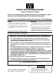
SAFETY AND WARNINGS SIGNS Replace If Missing Or Illegible One or more of these signs must be affixed on each machine as indicated, when not included as part of the front instruction panel. LOCATED ON THE OPERATING INSTRUCTION SIGN OF THE MACHINE: CAUTION PRECAUCION 1. Do not open washer door until cycle is completed, operating light is off, and wash cylinder has stopped rotating. 1.
EX 12, EX 22 Contents Introduction ........................................................................................... 1 Technical data ...................................................................................... 2 Installation ............................................................................................. 5 Installation of external liquid supply ...................................................... 9 Electro-Lube Dispenser ...................................................
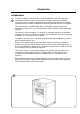
Introduction 1 Introduction Fig. The EX-FC model washer/extractor has been developed to cover the heavy duty requirements of hotels, motels, nursing homes, hospitals, professional laundries, restaurants, airlines, schools, colleges and all on-premises laundries where flexibility and quick formula variation, coupled with high quality automatic washing, are required.
Technical data 2 EX-12 FC Dry load capacity up to 30 lbs Overall dimensions Width Depth Height Net weight Dyn.weight 870 mm 900 mm 1302 mm 290 kg 34 1/4'’ 35 15/16'’ 51 1/4'’ 639 lbs 120 lbs./sqft Crated dimensions Volume Weight 1.25 m3 315 kg 44 cu.ft 695 lbs Inner drum Diameter Depth Volume 620 mm 412 mm 120 litre 24 7/16'’ 16 5/16'’ 4.4 cu.ft Speed of rotation Wash Distribution Low extract High extract 48 r.p.m. 78 r.p.m 340-510 r.p.m. 590-950 r.p.m.
Technical data 3 EX-22 FC Dry load capacity up to 50 lbs Overall dimensions Width Depth Height Net weight Dyn.weight 1000 mm 1102 mm 1412 mm 553 kg 39 3/8'’ 43 3/8'’ 55 9/16'’ 1218 lbs 157 lbs./sqft Crated Dimensions Volume Weight 2.05 m3 588 kg 72.3 cu.ft 1295 lbs Inner drum Diameter Depth Volume 750 mm 500 mm 220 litre 29 1/2'’ 19 11/16'’ 7.8 cu.ft Speed of rotation Wash Distribution Low Extract High Extract 44 r.p.m. 70 r.p.m. 300-460 r.p.m. 540-850 r.p.m.
Technical data 4 Outline and dimensions H C A D E 7 1 2 K L 5 4 3 M P B N O J G F Q 6 1 2 3 4 5 6 7 Opening for electrical cable connection Steam connection (optional) Cold water Hot water Hot water (only EX22) Drain outlet Soap box EX12 mm inches A B C D E F G H J K L M N O P Q R 870 1302 913 792 121 625 570 480 1100 – 240 120 1200 1110 85 203 433 34 1/4 51 1/4 36 31 3/16 4 3/4 24 5/8 22 1/2 18 15/16 43 5/16 – 9 1/2 4 3/4 47 1/4 43 11/16 3 11/32 8 17 R 2664 EX 22 mm inches 1000 1412
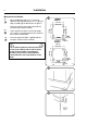
Installation Installation 5 2 The machine is delivered with expansion bolts and other items packed inside the drum. Shipping securities Fig. 2 The machine is shipped with four large metal brackets bolted to the suspension legs, as well as a support between the pulley and the back plate. Prior to installation, follow these steps: • Unpack the machine. Fig. 3 • Remove the lower front panel and the two rear panels. • Remove the support from the pulley at the back of the machine.
Installation 33 mm 1 5/16 in. 780 mm 30 23/32 in. 43 mm 1 11/16 in. EX22 996 mm It is of utmost importance that the machine is level, from side-to-side as well as frontto-rear. If the machine is not properly levelled, it may result in out-of-balance cutout without a real out-of-balance in the drum. 39 7/32 in. 910 mm 32 11/16 in. 7 • Insert the expansion bolts supplied with the machine. Fit the washers and nuts. 830 mm Fig. • Check that the machine is level and steady.
Installation Electrical installation Fig. 8 7 8 Connect L1, L2 and ground wires according to the markings of the terminal block. The cable is to hang in a large loose loop, supported by the clip of the terminal block. Although the machines are fitted with a thermal overload in the motor windings and separate fuses for the control circuit, a separate circuit breaker must be installed. Fig. 9 For proper overcurrent protection, check the data plate at the rear of the machine.
Installation 8 Water connection 10 NOTE All plumbing must conform to national and local plumbing codes. Fig. 10 Fig. 11 Incoming water lines do not require non-return valves, as the machine is already fitted with a siphon breaker. However, all incoming lines must be fitted with shut-off valves and strainers. • Water inlets are labelled for hot and cold water connection. • Flush the water system thoroughly and check that the strainer at the machine inlet is fitted correctly. Fig.
Installation Connection of external liquid supply 9 14 Remove cover and cover support over the soap box. Fig. 14 Fig. 15 Fig. 16 Bend all the way back the metal plate in compartment 3. Pull the knobs up and forward. 1. Loosen both knobs so that one side of the metal fingers underneath can slide under the top lid of the machine, within the supply box. 2. Fit the supply injector into the supply box so that both sides are held securely in places by the metal fingers.
Installation 10 Fig. 17 1. Drop the knob into the larger opening in the supply injector lid. 17 2. Tighten securely. Do not overtighten! Do not use pliers or other tools to tighten the knobs! Fig. 18 1. Stretch the multi-rubber ring B and select the correct size ring which will fit snuggly on the chemical tube you are using. Ring A is used for tubes with Ø 1/3" (8mm). 2. Use scissors or a razor to carefully cut out the proper size rubber ring.
Installation Liquid feed signal connection Fig. 19 11 19 To the right of the incoming power terminal block connection is the electrical connection block for supplying signals to an external supply injector. Depending on the number of signals needed, they shall be connected to terminals 1-4 with the common on C. The pumps obtain signals from the Hi-TEK PC-board. NOTE! Common terminal C has no direct connection to L1/L2 on the incomming power terminal block.
Electro-Lube Dispenser 12 Instruction for setting timing on electro-lube oil dispensing Fig. 20 Fig. 21 20 Pry off the switch panel cap with a screwdriver. • Under the cap are the switches for time setting. • Set the "Light" and "12M" dip switches to the "On" position. Make certain all other switches are in "Off" position. Fig. 22 • The light will start flashing after a few minutes and will continue to flash every 15th to 20th seconds as long as the dispencer is in operation. Fig.
Installation Steam connections (optional steam heating) 13 24 Steam pressure required: • minimum 7 PSI • maximum: 110 PSI • recommended: 40-85 PSI A steam valve for this machine type is fitted separately in a bracket on the upper rear cover plate. The steam valve, hose and filter are supplied with the machine. Steam-flush all pipes and hoses before connection. Installation instructions: 1254 25 • Install rear cover plates. Fig. 24 Fig. 25 Fig. 26 • Install steam valve bracket and valve.
Installation 14 28 STEAM HOSE APPROVED FOR min. 0,1 MPa max.
Installation 15 Steam connection (compressed air operated) The following steam pressure values apply: • min: 10 psi • max: 110 psi • recommended: 25-85 psi Before they are connected, pipes and hoses should first be flushed out with steam. Procedure:. Fig. 29 • Fit the steam valve. • Fit the steam hose between the steam valve and the machine's steam inlet. • The steam supply line must be fitted with a manual shut-off valve. Fit the filter on the shut-off valve.
Installation 16 Start-up and safety checklist 30 Before initial start-up of a Wascomat washerextractor, the following safety checks must be performed: Fig. 30 • Make sure that all electrical and plumbing connections have been made in accordance with applicable local codes. • Use only flexible water fill and drain hoses of the proper length to avoid sags and kinks. • Make sure the machine is properly grounded electrically.
Installation Function control check-out list 17 33 In the machine cylinder, you will find the warranty registration card, a copy of the warranty policy and other pertinent material. The warranty card should be completed and sent to Wascomat. All other items should be placed in a safe place for future reference. The machine should be cleaned when the installation is completed, and checked out as detailed below without loading the machine with fabrics: 1.
Function check 18 Function checks Fig. 34 34 After installation the machine should be cleaned and an empty-machine test program with detergent carried out. Close the door. Open the manual water and steam valves. Add detergent and conditioner. Fig. 35 Fig. 36 Choose program 6 by entering two numbers 06. Press START to begin test cycle The machine will start up and the display window will show cycle information.
Safety Rules Safety rules • This machine is designed for water washing only. • Machines must not be used by children. • All installation operations are to be carried out by qualified personnel. Licensed personnel are necessary for all electric power wiring. • The interlock of the door must be checked daily for proper operation and must not be bypassed. • All seepage in the system, due to faulty gaskets etc., must be repaired immediately.
Mechanical and electrical design 20 General Fig. 37 These machines are free-swinging models i.e. the outer drum and motor bridge are suspended in the machine chassis via a spring suspension with a strong spring in each corner of the machine. Each spring has a shock absorber which dampens the movement of the machine. The inner drum is driven by a motor via a V-belt: one motor is used washing and distribution speed and for extract speeds.
Mechanical and electrical design The washing machines are controlled by a microprocessor program unit. This provides several major advantages: • The control of times, levels and temperatures takes place with considerable precision and flexibility • The large character display provides detailed information in clear text about the different wash programs, the machine's different activities, relevant wash times and temperatures.
Mechanical and electrical design 22 Frame Description Fig. 38 The frame is constructed on the free-swinging principle, i.e. the washing drum is freely and resiliently suspended in the fixed frame. The entire frame is constructed of U-shaped iron beams forming a stable and torsionally rigid structure. The suspension device for the drum unit and motors consists of four posts, one in each corner, each with a robust spring to which the washing drum supports are attached.
Mechanical and electrical design 23 Drum with bearings Description Fig. 39 The inner drum is journalled to the outer drum by two robust bearings in a bearing housing which is bolted to the rear plate. The bearing unit supports the drum without any support being needed at the front. Shaft seals of the V-type, as well as O-rings, seal against leakage. The space between the bearings is packed with grease during assembly. No additional grease is required.
Mechanical and electrical design 24 Safety locking device The machine safety locking device includes a safety interlock system which prevents personal injury through the following precautions: • The machine cannot be started until the door is shut. • The door is automatically locked when the machine starts. • It is not possible to open the door until 2-3 minutes have elapsed after the washing program has ended. This ensures that the drum is motionless when the door is opened.
Mechanical and electrical design 25 Rotation guard Description The rotation guard checks that the machine is completely at a standstill before the door can be opened. When the drum has been at a standstill for approx. two seconds the solenoid in the door lock is deactivated and the lock can be opened (provided that the machine has been emptied of water and the programmer has reset). The rotation guard also checks that the drum is revolving when the wash or extraction relays are operating. Fig.
Mechanical and electrical design 26 Fault location Door does not unlock Conditions: wash program ended and drum at a standstill Measure the voltage between the following points: 1. X93:2 - X93:3 Should be 0 V DC. If the voltage is 220 V AC, check the rotation guard. 2. X193:1 - X193:2 Should be 0 V DC. If the voltage is 220 V AC, check the rotation guard and the cables between rotation guard and delay unit. 3. X194:1 - X194:4 Should be 220 V AC.
Mechanical and electrical design 27 Function If the machine has not been energised within the last three minutes, the door will remain unlocked. When the machine is energised the door will be locked if a program is activated or if the drum is rotating. Upon completion of a program the door will be unlocked automatically as soon as the drum has stopped rotating.
Mechanical and electrical design 28 Control unit The control panel (1), mounted at the front, includes all components necessary for operating the machine, such as display window, control switches and a key-operated switch. Fig. 43 The printed circuit board with the microprocessor electronic timer is mounted just behind the control panel. B31 Rotation guard for sensing that the drum has stopped before the door can be opened.
Mechanical and electrical design 29 44 Relays The FC models employ relays to control the following: • switching between powder and liquid detergent. • drain to tank. • pump from tank. } for optional recovery and recycling • motor operation. Construction Fig. 44 The body of the relay holding the stationary contacts is made of current-resistant plastic. A solenoid and a contact bank hold the moving contacts. The contacts are spring-loaded to assure the correct contact pressure.
Mechanical and electrical design 30 Motor In machines with frequency control the same motor is used for wash speed, distribution speed and extraction. The motor is located on a motor mounting plate, and drives the drum via a belt. The tension of this drive belt can be altered by moving the entire motor mounting plate thanks to the mounting slots on one side. The motor has a thermal cut-out located in its windings.
Mechanical and electrical design Program start 31 46 The following conditions must be fullfilled before the motor can start: High extraction • Motor not overloaded. • Door shut. • Go-ahead signal from programmer. When the door is locked relay K71 is activated feeding power to the electronic control unit and the motor is allowed to start. Extraction Fig. 46 For extraction the programmer sends signals for either low or high extraction.
Mechanical and electrical design 32 Repair instructions 47 Overheated motor, motor not running • Wait till motor has cooled down. Motor guards are automatically reset after 30 minutes. Restart. • Possible cause of motor guards releasing repeatedly: short circuiting. In both cases the motor should be replaced. A Very noisy motor • Breakdown of bearings – replace motor.
Mechanical and electrical design Fig. 33 Loosen the screws holding the motor mounting plate on the motor side. Lower the motor mounting plate until the correct belt tension is obtained, as shown in Fig. 45. Secure the motor mounting plate in place. 47 Motor control On the motor control circuit board there is a yellow LED which indicates various types of fault: Fig. 48 48 4 1 Fuse XM1 3 6 1 XM4 2 (XM6) (XM3) 8 XM2 1 LED for error indication (XM5) Indication Cause The LED flickers.
Mechanical and electrical design 34 In two cases the machine will be halted without indication: • Overvoltage in feed. • Motor and/or motor control overheated. Motor does not operate when it should • Check the voltage feed to the motor control unit by: - Disconnecting XM4 (quick connector) - Using a voltmeter (AC) to measure between pins XM4:1-2. Correct value = 220 V (208 - 240 V) - Using a voltmeter (DC) to measure between pins XM6:1-4. Correct value = 250 - 375 V. If not check fuse. Replace unit.
Mechanical and electrical design Supply injection valve 35 49 Construction Fig. 49 This valve has a single-inlet with three outlets, each with its own solenoid coil. The body is made of heat-resistant polyamid plastic and the solenoids encased in water-tight plastic. The electrical connector terminals are spade lugs. A filter screen on the inlet side prevents dirt from entering the valve. Flow restrictors can be placed at either the inlet or any of the outlets. Operation Fig.
36 Mechanical and electrical design Repair instructions 51 Limescale can block the hole in the valve diaphragm and interfere with the function of the valve. Fig. 51 It is therefore advisable to dismantle and clean the valve at certain regular intervals. The frequency depends on operating conditions and the level of contamination in the water. If the valve does not open • Check that power is supplied to the coil.
Mechanical and electrical design Inlet valve - EX22 Fig. 54 37 54 The water inlets have brass bodies with a larger cross section of the outlet in order to acheive a shorter filling time for the machine. Construction The valve housing is made of pressed brass. The spring-loaded plunger is made of stainless steel and located at its lower end is a rubber gasket for the pilot valve.
Mechanical and electrical design 38 Soap supply box Fig. 57 The three-compartment soap supply box is located at the top of the machine. Viewed from the front, the compartments are marked with figures 1, 2 and 3. Compartment 1 and 2 are used for adding detergent directly to the wash. Compartment 3 is used for adding fabric softener. All three compartments can be programmed individually. For liquid supplies compartment 2 is only used together with a top mounted supply injector connection.
Mechanical and electrical design Drain valve 39 58 Description Fig. 58 The drain valve consists of a bracket (1), on which are mounted the motor and gear (2) and diaphragm (3). The rubber diaphragm is resistant to a water temperature up to 100°C (212•F). The installation of a lint trap is not necessary. The machine is equipped with an overflow, which bypasses the drain valve. The drain can be cleaned by removing the drain connection (4) outside of the machine or by removing the rubber diaphragm (3).
Procedure 40 Procedure for use All operations, including the programming of new wash programs are carried out from the control panel on the front of the machine. During normal use, the programming keys to the left of the panel are inoperative. Fig. The control panel comprises the following: 59 • a display window with four lines each of 40 characters. This shows the relevant program information, the programming instructions, error messages etc.
Procedure Preparation 41 60 • Sort the wash according to the washing instructions on the garment labels. Check that there are no foreign objects in the garments. Pull up zipper fasteners. • Open the washing machine door, check that the drum is empty, insert the wash goods and close the door. Automatic washing The manual controls can be used during automatic washing. Program selection When supplied, the machine is provided with a number of standard programs (program numbers 01-09).
Procedure 42 Program information Fig. 62 62 When a program has been selected and PROG. INFO. is pressed, further information about the program is shown in the display window's bottom three lines (see ''TEXT'' in programming section). Measuring the detergent Fig. 63 Fig. 64 Five lights on the panel indicate which detergent compartments will be used, or supply signals provided during washing. Will be lit when specific detergent compartment is used, or signal provided.
Procedure Starting the program 65 Fig. 65 Fig. 66 43 Press START/HOLD/RAPID ADV. button. The wash cycle will commence and the display window will display wash information as shown in the figure below. Temporary stop Fig. 65 Fig. 65 • Press START/HOLD/RAPID ADV.. All active functions (motor, filling with water and heating) are switched off. The drain will remain closed and the door locked. START HOLD/RAPID ADV. HEAT LOW EXTR.
Procedure 44 Programmed stop Fig. 67 If there is a programmed stop in the program, the machine stops and a buzzer sounds. The buzzer is switched off by pressing START/ HOLD/RAPID ADV. The program is restarted by pressing the button again. 67 Tumble drying after the program is completed Fig. 68 If the DOOR LOCK and MOTOR buttons are pressed before starting or while a program is operating, the drum will continue to rotate after the program is completed. The drum is stopped again by pressing MOTOR again.
Procedure Manual washing Fig. 69 Fig. 70 Fig. 71 Fig. 72 45 69 • The indiciator lamps above the control buttons indicate that the function is active. COLD WATER, HOT WATER and FLUSH must be kept pressed to remain active. Other control buttons change function (ON-OFF) each time they are pressed. • Lock the door by pressing DOOR LOCK (the lamp above the shall light up). Note that the door must be locked for other manual operations to be possible.
Procedure 46 Extract cycle 74 For safety reasons, there is no manual button for the extract cycle. There are two choices if extracting is required during manual operation: • 1. Select one of the standard programs and fast forward to the "Extract" cycle. DRAIN MOTOR CLOSED FLUSH PROG. INFO. DOOR LOCK °C/°F • 2. Program your own program by draining and extracting for the required time.
Procedure Fig. 78 The machine has two thumb wheel switches for determining the speed for low and high extraction. 47 78 The value on these switches can be changed while the machine is in operation. The time for low extraction (Switch 1) shall be programmed under question ''Low extraction XX min XX sec'' and high extraction (switch 2) under question ''High extraction XX mini XX sec''.
Programming 48 General Fig. 79 The washing machine’s program operation is controlled by a microcomputer and the wash programs are stored in an electronic memory. Program controls are very exact and the wash programs can be easily adapted to the end user’s individual requirements. The machine is supplied with a number of fixed basic programs which cannot be deleted or modified. However, they can be used as a background for programming end user programs.
Programming Programming - general description Programming can be divided into two categories: Programming a completely new program or using an old program as a background. Programming a completely new program Fig. 80 The wash program is constructed by selecting different sub-programs with the buttons on the panel. These sub-programs, when stored after each other, form the complete final wash program. Sub-programs can be selected in an optional sequence.
50 Programming Using and old program as a background Fig. 81 In this operation, an old program is selected as a background for the new one. The answers to the questions and the written texts can be changed to create a new program. Furthermore, subprograms can be erased and new sub-programs entered in optional positions. When the changes are complete, the new program is entered under a new program number.
Programming Controls 51 82 The key switch Fig. 82 Turn the switch to the PROGRAM position if the wash program is to be programmed or changed. If for any reason you wish to discontinue programming and start again, turn the switch to the RUN position and then back to PROGRAM again. Any programming that you have done so far will be deleted but other programs already stored will not be affected. RUN PROGRAM ENTER Fig.
Programming 52 Erase Fig. 85 85 This button can be used in three different ways: PROGR. MODE SELECT SEQUENCE PREWASH 01 • Deleting a complete program. Press ERASE when the display window displays the adjacent text. A warning text will then be displayed. Press ENTER, enter the program number with the number keys and press ENTER again. Fig. 86 87 RA- ERASE DERA Number keys ENTER KLAR ENTER KLAR • Deleting a section of a program.
Programming YES, NO, number keys Fig. 89 These keys are used to answer the different questions which are found under each subprogram. All answers must be followed by pressing ENTER for the answer to be registered. 53 89 PRE MAIN WASH WASH DRAIN EXTR. TEXT TEXT Fig. 90 The key for TEXT is used for entering the explanatory text which is displayed when PROG.INFO. is pressed after that a program is selected.
Programming 54 Programming a new program 93 If you make a mistake or get stuck, there is always a final resort: RUN Turn the key to the RUN position and then to PROGRAM again. Any programming you have carried out so far will be lost but other programs will not be affected. PROGRAM Turn the key Fig. 93 Turn the key to the PROGRAM position. The first character will then be displayed in the display window. 0167 94 PROGRAMMING MODE: DO YOU WANT AN OLD PROG.
Programming Answering questions The general principle for answering questions is the same for all sub-programs: • The cursor (the flashing square) is always to the right of line three in the display window. This means that it is the question on line three that is to be answered. Fig. 96 97 Fig. 98 Fig. 99 96 PROGR.
Programming 56 The following is a summary of the different questions that can appear under the different buttons. 100 PROGR.MODE SELECT SEQUENCE PREWASH PAUS WITH BUZZER Y/N NORMAL ACTION DURING FILLING Y/N 01 N N NOTE: The questions which are described do not apply to all machines. On certain types of machines, some of the values are programmed as standard values and need therefore not be answered. Press: YES JA KLAR ENTER or RED. EDIT RED.
Programming Refilling Fig. 104 LEVEL RESET is value which regulates at which level water is to be refilled if the water level drops while a wash is in progress. 57 104 PROGR. MODE SELECT SEQUENCE LEVEL 000 UNITS LEVEL RESET 000 UNITS TEMPERATURE 000 °C PREWASH 01 Example: The following values are programmed: Press: • Level: 130 units Number keys • Level reset: 10 units KLAR ENTER or EDIT RED. JA DOWN NED This means that: • Water is filled to level 130 at the beginning of the sub-program.
Programming 58 Water filling FIg. 107 107 One or several water valves can be selected. PROGR.MODE SELECT SEQUENCE PREWASH WASHTIME 00 MIN. 00 SEC. COLD WATER Y/N HOT WATER Y/N If you decide to use hot and cold water, both valves will be open while filling is in progress. The hot water valve will be automatically closed if the pre-set temperature is exceeded. The valve will open again if the temperature drops below the preset value.
Programming Drain 110 Pause with signal Fig. PROGR.MODE SELECT SEQUENCE DRAIN If the question is answered with YES, the washing machine will stop before the sub-program starts and a buzzer will sound. 110 59 PAUSE WITH BUZZER Y/N NORMAL ACTION Y/N JA YES Select the method of working while draining. Distribution action is used before a spin cycle so that garments are equally distributed around the drum. 111 RED. RED. EDIT DOWN NER NED 111 PROGR.
Programming 60 Programming complete • When ’’END OF SEQUENCE’’ appears on the third line of the display window and all questions are answered, press EDIT DOWN. 114 PROGR.MODE SELECT SEQUENCE EXTRACT TIME HIGH SPEED TIME LOW SPEED • Answer NO to the question ’’END PROG. SESSION Y/N?’’ if there are more subprograms to be answered. Answer YES if the sub-program is the last in the completed program. The continue under the heading ’’Looking through the program’’. 00 MIN. 00 MIN. 00 SEC. 00 SEC.
Programming Special cooling valve FIg. 116 Answer YES is there is a separate water valve use for cooling. If the answer is NO, the standard cold water inlet is used. 61 116 PROGR.MODE SELECT SEQUENCE COOL DOWN PAUSE WITH BUZZER Y/N SEPARATE COOL DOWN VALVE Y/N GENTLE ACTION Y/N 01 N N N Gentle action Fig. 117 Press: Answer YES if the machine is to operate on gentle action during cooling. The machine will operate on normal action if the answer is NO. JA YES KLAR ENTER or RED. EDIT RED.
62 Programming Example: 120 • ON TIME 212-158°F (100-70°C) 8 seconds. • ON TIME 158°F (70°C) - END 13 seconds. • END TEMP. 113°F (45°C). • Wash temperature 194°F (90°C). The following takes place: Fig. 120 • When the water in the drum reaches 194-158°F (90-70°C), the water valve is ON 8 seconds, OFF 22 seconds, ON 8 seconds, OFF 22 seconds etc. providing the temperature in the drum does not decrease by more than 7°F (4°C)/minute.
Programming Text 63 123 Each program can be provided with two types of informative text: Fig. 123 Fig. 124 • 1. A program name which is always displayed when the program is selected when washing. This text is programmed when the program number is selected. See under the heading ’’Program names’’ later on in the manual. SELECT PROGRAM TOW DIGITS PROGRAM 01 HEAVY SOIL START WASH WITH START-BUTTON FOR PROGRAM INFO. PRESS PROG.INFO • 2.
Programming 64 Times for normal action and gentle action Fig. 127 Fig. 128 The times for rotating and stationary drum during normal and gentle action can be programmed. All times can be selected within the range of 0-30 seconds with 1 second intervals. 127 PROGR.MODE MAINDATA BUZZER ON WHEN PROGRAM FINISHED Y/N GENTLE ACTION ON TIME 00 SEC. GENTLE ACTION OFF TIME 000 SEC. Press ENTER when ’’TO END. PRESS ENTER’’ is displayed in the display window. Press: Number keys Entering the program number Fig.
Programming Program names Fig. 131 You can now give the program a name which will be displayed when the program is selected during washing. The text can be up to 29 characters long. 65 131 -ABCDEFGHIJKLMNOPQRSTUVWXYZ !&/()=?;:,.* PROGRAM 10 - The way in which text is entered described under the heading ’’TEXT’’ earlier in the manual. Press: Saving programs Fig. 132 Fig. 133 Fig. 134 EDIT UP When the program has been given a name, the program is saved in the program memory.
Programming 66 Starting from a previously saved program 135 If you make a mistake or get stuck, there is always a final resort: RUN Turn the key to the RUN position and then to PROGRAM again. Any programming you may have carried out so far will be lost but other programs will not be affected. PROGRAM 0167 Turn the key Fig. 135 Turn the key to the PROGRAM position. The first question will now be displayed in the display window. 136 PROGRAMMING MODE DO YOU WANT AN OLD PROG.
Programming Fig. 139 Fig. 140 The cursor will appear on the first line of this subprogram. Use EDIT UP and EDIT DOWN to move within the sub-program to reach the line(s) to be altered. 67 139 PROGR.MODE SELECT SEQUENCE MAINWASH 01 PAUSE WITH BUZZER Y/N NORMAL ACTION DURING FILLING Y/N NOTE Press: ENTER is to be used only as an acknowledgement when sub-questions are to be altered. Use buttons EDIT UP and EDIT DOWN to move around within the program. EDIT DOWN NO ENTER 0225 Fig. 141 Fig.
Programming 68 NOTE Use only EDIT UP and EDIT DOWN for looking through the program. ENTER shall only be used for making changes in the program. 143 PROGR. MODE SELECT SEQUENCE PREWASH PAUS WITH BUZZER Y/N NORMAL ACTION DURING FILLING Y/N GENTLE ACTION DURING FILLING Y/N 01 Y Y N Press: Making changes to the program FIg. 143 Use EDIT UP and EDIT DOWN so that the question to be changed is on the third line in the display window. The cursor (the flashing square) is on the far left of line three.
Programming Altering text The text that is displayed when a program is selected and PROG.INFO is pressed can be altered. Fig. 147 Fig. 148 69 147 PROGR.MODE SELECT SEQUENCE Go to the position between two sub-programs (see the section ’’Looking through the program’’). Press TEXT and ENTER. Any text that might have been programmed in the old program is displayed. Press: TEXT TEXT Refer to heading ’’TEXT’’ earlier in the manual when entering text. 0233 148 -ABCDEFGHIJKLMNOPQRSTUVWXYZ !&/()=?;:,.
Service information 70 Service information Fig. 151 The machine's electrical power connection cable shall be provided with a safety ground to avoid breakdowns in the machine's electronic program controls. If interference problems do occur, check first that the machine is properly grounded. The machine's operation in terms of safety and function is continuously monitored by the program unit.
Maintenance Maintenance 71 152 Preventive maintenance has been reduced to a minimum by the careful design of reliable components and material. However, the following, measures should be taken at regular intervals and in proportion to the hours of service. IMPORTANT! Make certain that all electrical power to the machine is shut off before removing top or rear panels. Daily • Check the door lock and interlock before starting operations.
Trouble-shooting 72 Trouble-shooting 154 If machine does not start Fig. 154 A Check circuit breaker in the power feed line to the machine. B Check door safety switches. C Check glass cartridge fuses. D Check for fault indication on display (see under the heading ''Service information''). If water does not drain Fig. 155 A Check for fault indication on display (see under the heading ''Service information''). B Check drain valve and solenoid for proper operation.
Trouble-shooting If machine does not extract Fig. 156 73 156 A Check for fault indication on display (see under the heading "Service Information"). If motor does not operate at wash speed. Fig. 157 A Check for fault indication on display (see under the heading "Service Information"). B Check motor and V-belts.
Trouble-shooting 74 If machine runs slowly on wash speed or there is a slapping or thumping noise. Fig. 158 A Replace V-belts 158 If a metallic noise can be heard at rear of machine. Fig. A Tighten lock screw on pulley on motor shaft. 159 If the door is leaking. Fig. 160 A Check door gasket. If gasket is in good condition, check the tension between door gasket and door frame and adjust.
Trouble-shooting If there is leaking around the glass. Fig. 161 75 161 A Re-cement glass in door gasket, if worn. Replace door gasket if worn. If water does not enter the machine. Fig. 162 A Check for fault indication on display (see under the heading "Service Information"). B Check the valve coils on inlet valves. C Check wires leading to electric coils. D Be sure manual shut-off valves are in open position.
76 Trouble-shooting If water continues to fill without stopping. Fig. A Check for incorrect programming. 163 B Check hose attached to level control unit on the printed circuit board. 163 C Check inlet valves for dirt underneath the valve diaphragm. To localize, shut off power. If water continues to flow, inlet valves have foreign material in them and should be thoroughly cleaned. If water continues to flow without filling machine. Fig.
Trouble-shooting If machine vibrates excessively. Fig. A Check the out-of-balance detector switch. 165 B Check the shock absorbers and the springs of the drum suspension. 77 165 If safety fuse blows at the beginning of the cycle. Fig. A Replace fuse. 166 B Disconnect wires leading to the delay circuit of the door lock. Replace fuse and start. If the machine now works, replace delay circuit. NOTE The electronic timer has a built in service program that can be useful when troubleshooting.