
Manual

8
2600 Emrick Blvd • Bethlehem, PA 18020 • USA • 800-922-0085 • www.warrencontrols.com
INSTALLATION
Recommended Piping: ANSI 125 Flanges should mate with piping with 125 Lb or 150 Lb
Flat Faced Flanges.
Per ISA Recommended Piping Practices. Control valves perform best with a reasonable
amount of upstream and downstream straight pipe prior to elbows and strainers. The
general specification for this is 16 pipe diameters upstream of straight pipe and 5 pipe
diameters downstream of straight pipe as minimums. However, this is a broad specification
covering all pipe diameters and velocities. Many applications do not have this kind of
space. While more length of straight pipe is desirable, Warren Controls has produced a
table of minimum pipe diameters for use on our PICV. Failure to follow these guidelines
may lead to noticeable vibrations or noise for excessive turbulence in some applications
with significant head pressure. In the unlikely event of excessive noise or vibration, other
remedies like special low noise trim may be available but at the expense of the user or
installer when not following installation guidelines.
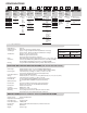
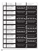
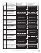
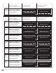
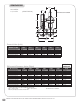
PRODUCT MODEL
(where ‘x’ is a configurable option)
LOW DP SPRING
PERFORMANCE
MEDIUM DP SPRING
PERFORMANCE
FLANGE
PN16
P1222Fx-xxxx-P12Dx-2x
DN250 Standard Port
PN16
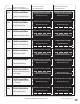
P12222S-xxxx-P12Dx-2x
DN250 2 Sizes Reduced Port
SS Trim Only
PN16
P12221S-xxxx-P12Dx-2x
DN250 1 Size Reduced Port
SS Trim Only
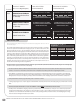
The above tables are recommended minimum lengths for good and stable performance. Wherever possible, longer runs of straight pipe
should be used for optimal performance and stability.
• Besurethattheflowmedium,ambienttemperatureandtheselectedlocationwillnotexceedthemaximumtemperatureofthePICV,
actuator, or accessories. Information can be found on the nameplate and product specifications regarding these limits.
• CheckPICVforanydamageduetoimproperstorageortransportation.Immediatelynotifyyoursalesorganizationofanydamaged
goods upon receipt. Do not attempt to move or disturb them further so photos may be taken. If the shipping container is noticeably
damaged, refuse receipt as the shipping company should be held liable, until a shipping representative is available to take photos.
• VerifythatthePICVisvisuallyingoodworkingorder–notbentorcracked.
• Followgoodpipingpractices.InstallabypassaroundthePICV.Installstopvalvesininletandoutletpipingtoprovidemeanstoisolate
PICV.
• THEPICVSHOULDBEINSTALLEDASAUNIT.THESEGMENTSSHOULDNOT BE SEPARATED FOR INSTALLATION.
• CarefullyremovethePICVfromshippingcratewithaportablehoistorcrane.ThePICVistooheavyforoneoreventwopeopletolift
and hand-install depending on size. The Crane or Hoist should use a strap or chain cradle around the central flanges of the two valve
assemblies to raise and maneuver the PICV into position at the pipe flanges. Efforts should be made to avoid damaging the sensing
lines and actuators during this installation procedure.
Set Differential Pressure (BAR)
0.14 0.21 0.29 0.37
Maximum flow (LPS)
66 81 95 107
Set Differential Pressure (BAR)
0.39 0.45 0.5 0.55
Maximum flow (LPS)
110 118 125 131
Set Differential Pressure (BAR)
0.14 0.21 0.29 0.37
Maximum flow (LPS)
76 92 109 123
Set Differential Pressure (BAR)
0.39 0.45 0.5 0.55
Maximum flow (LPS)
126 135 143 150
Set Differential Pressure (BAR)
0.14 0.21 0.29 0.37
Maximum flow (LPS)
86 106 124 140
Set Differential Pressure (BAR)
0.39 0.45 0.5 0.55
Maximum flow (LPS)
144 155 163 171
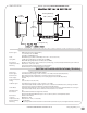
PICV Minimum Lengths of
Straight Pipe
PICV Size Upstream
Straight Pipe
Downstream
Straight Pip
2 ½” (DN65) 16” (40.64 cm) 12” (30.48 cm)
3” (DN80) 16” (40.64 cm) 12” (30.48 cm)
4” (DN100) 16” (40.64 cm) 12” (30.48 cm)
5” (DN125) 24” (60.96 cm) 12” (30.48 cm)
6” (DN150) 32” (81.28 cm) 12” (30.48 cm)
8” (DN200) 36” (91.44 cm) 14” (35.56 cm)
10” (DN250) 40” (101.6 cm) 16” (40.64 cm)