
Manual

3
PRESSURE INDEPENDENT CONTROL VALVE PICV_IOM_REVF_0114
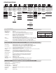
DPRV DOUBLE ACTING DIAPHRAGM ACTUATOR WITH SPRING ASSIST
Control Signal: Differential Pressure from Control Valve,
2.0 to 8 PISG (0.14 to 0.55 BARD)
150 PSIG (10.3 BARD) Max Static
Fluid: Chilled Water Typical, Water or Water/Glycol from 35 °F- 180°F (2°C - 82°C )
Spring Pack: Low DP Spring: Adjustable 2 to 6 PSIG (0.14-0.41 BARD)
Medium DP Spring: Adjustable 5 to 8 PSIG (0.34-0.55 BARD)
Construction: Cast Gray Iron Class G3000, epoxy coated, epoxy coated spring, SS components, Woven Buna-N, nylon reinforced.
Temperature Limits: Ambient 32°F - 122°F ( 0°C - 50°C )
Mounting: Factory Aligned, Vertical Above Centerline of Control Valve
Consult factory for preconfigured alternate orientations
ELECTRIC ACTUATOR SPECIFICATIONS (TR5000-X)
Valve Usage: 5, 6, 8, & 10 inch, DN125, DN150, DN200, DN250
Control Signal: 4-20 mAdc (Factory Setting), 0-10 Vdc, 2-10 Vdc, or 0-20 mAdc; Field Selectable (Dip Switch)
Control Action: Direct Acting, Actuator Shaft Extends on Increasing Signal (Factory Setting) or
Reverse Acting, Actuator Shaft Retracts on Increasing Signal; Field Selectable (Dip Switch)
Power Supply: 220 VAC
Power Consumption: 12VA
Timing: 90.68 Seconds / Inch (3.57 s/mm)
Feedback Signal: 4-20 mAdc (Factory Setting), 0-10 Vdc, 2-10 Vdc, or 0-20 mAdc
Field Selectable (Dip Switch); Feedback Signal Increase as Actuator Shaft Extends (Factory Setting) or Feedback
Signal Increases as Actuator Shaft Retracts; Field Selectable (Dip Switch)
Failure Mode: Fail Actuator Shaft Retracted on Loss of Signal (Factory Setting) or Fail Actuator Shaft Extended on Loss of Signal
Field Selectable (Dip Switch); Actuator Shaft Fails In Last Position on Loss of Power
Manual Override: Yes
Construction: Die Cast Aluminum Motor Housing & Yoke. Painted.
Case Has Two PG11 Cable Glands Accepts 0.197 to 0.394 inch (5mm to 10mm) Diameter Cable
Connections: Coded Screw Terminals
Locations: NEMA Type 3 / IP54
Temperature Limits: Ambient 14˚F to 122˚F ( -10˚C to 50˚C )
Relative Humidity: < 95% RH (40ºC)
Mounting: Factory Aligned, Vertical Above Centerline of Control Valve; Consult factory for preconfigured alternate orientations
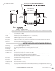
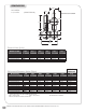
4X 0.31 in (0.79 cm)
THRU MOUNTING FOOT
8.75 in (22.23 cm)
6.69 in (16.99 cm)
6.72 in
(17.O7 cm)
4.91 in
(12.47 cm)
6.97 in
(17.7O cm)
5.19 in
(13.18 cm)
1/2 in (1.27 cm)
8.5 in (21.59 cm)
VMS-25 BCM