
User Manual


6
2600 Emrick Blvd • Bethlehem, PA 18020 • USA • 800-922-0085 • www.warrencontrols.com
IOM_AA_RevH_0413
ON
1 2 3 4 5
Rotation: CW
Input in Vdc
Feedback in mA
Fail safe return at 0º
Special, see below
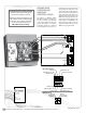
Potentiometer
Dip switch
Reset button
LED
Terminal
Clutch
High voltage terminal
TB4
RETURN
HOT/LIVE
Fuse
1 2 3 4 5
TB1
ON
1 2 3 4 5
DS1
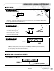
Dip switch settings
ON
1 2 3 4 5
Rotation: CCW
Input in mA Feedback in Vdc
Fail safe return at 90º
Special, see below
Factory default
Special (dip #5)
5
Linear lift
Analog input
5
Normal
Analog input
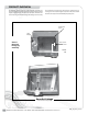
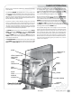
WIRING AND
STARTING AN
AMURACT
CONTROL VALVE.
This applies to all AmurAct models.
Remove the screw from the black mo-
tor cover and refer to the following
circuit board diagrams for the des-
ignated terminations and switches.
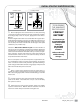
Field wiring should be of sufficient
size and insulation rating to be in ac-
cordance with local codes, ordinances
and standards for safety. The motor
draws 30VA (either model) at full load,
while start up power consumption is
50VA. The Power Supply wires if not
specified should be a minimum of 18
AWG and at that gauge should not ex-
ceed 100 ft. from the transformer. For
longer lengths, use 16 AWG wire. The
input signal and feedback may use
standard instrument wire of 24 or 26
AWG. Do not use rigid conduit.
* Fuse is a
part number
3720315041
315 mA
Slow Blow with
T41 terminations
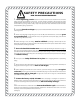
Contact the factory at (610) 317-0800
before attempting to reconfigure or
reposition an AmurAct actuator.
Improperly rotating the linkage on the
valve bonnet adversely affects linkage
calibration, can result in seat damage
and/or operational failure; and
will void warranty coverage.
ON
1 2 3 4 5
Rotation: CW
Input in Vdc
Feedback in mA
Fail safe return at 0º
Special, see below
Potentiometer
Dip switch
Reset button
LED
Terminal
Clutch
High voltage terminal
TB4
RETURN
HOT/LIVE
Fuse
1 2 3 4 5
TB1
ON
1 2 3 4 5
DS1
Dip switch settings
ON
1 2 3 4 5
Rotation: CCW
Input in mA Feedback in Vdc
Fail safe return at 90º
Special, see below
Factory default
Special (dip #5)
5
Linear lift
Analog input
5
Normal
Analog input
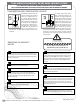
TB1
Non-linear lift
Clutch
LED
Reset
Button
Dip Switch
Terminal
TB5
(2-way only) (2-way or 3-way)