
Instruction Manual

9
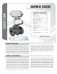
Series 5800 5800_IOM_RevB_0413
See also separate actuator and accessory instructions
for additional installation guidelines.
-
ed location will not exceed the maximum temperature of the valve,
actuator, or accessories. Information can be found in the product
specifications and on the nameplate(s) regarding these limits (See In-
formation Present on Control Valves section for location of important
information on valve).
-
stall stop valves in inlet and outlet piping to provide means to isolate
valve.
-
stream of the valve and 20 pipe diameters downstream of the valve.
-
er.
water hammer or possible erosion in equipment.
-
ing adjustment and operation.
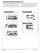
position with the stem pointing upward.
-
ported independent of the valve. DO NOT MOUNT DL115 ACTUA-
TORS IN THE HORIZONTAL POSITION.
Dimen-
sions & Weights of Product Specification section for actuator removal
clearance).
scale, chips, welding spatter, and foreign material. Thoroughly blow
out or flush pipe lines.
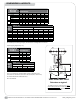
direction(s). For proper operation in all applications, control valves
must be piped according to the corresponding flow arrows, inlet
markings, and port markings present on each valve (See Information
Present on Control Valves section for location of important informa-
tion on valve).
of the valve body or to the first two threads of the pipe.
excessive stress and the possibility of cracking.
INSTALLATION
Check valve for any damage
due to improper storage or
transportation. Immediately
notify your sales organization
of any damaged goods upon
receipt. Do not attempt to move
or disturb the valve further
so photos may be taken. If the
shipping container is noticeably
damaged refuse receipt, as
the shipping company should
be held liable until a shipping
representative is available to
take photos.
!