
Owners manual

©2013 Warn Industries, Inc. WARN® and the WARN logo are trademarks of Warn Industries Inc. 7 91853A0
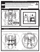
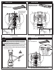
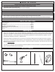
12. INSTALLATION 13. INSTALLATION
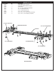
(2) U-bolt
(4) 5/16 - 18 Locking Hex Nut
Figure 13: Tighten all hardware to torque specications in chart below.Figure 12: Loosely fasten rear contact plate to rear u-bolts with locking nuts.
(4) U-bolt
(8) 5/16 - 18 Locking Hex Nut
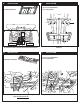
(6) 3/8 - 16 x 3/4- Carriage Head Bolt
(6) 3/8 - 16 Locking Hex Nut
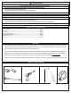
TORQUE SPECIFICATIONS
Please use the recommended torque specications when assembling this product unless otherwise specied.
FASTENER SIZE FASTENER TORQUE Socket /Wrench Size
lb-ft (N.m)
5/16" U-bolt 17 (23) 1/2” socket
3/8" Carriage Bolt 30 (40) 9/16” socket
PRE-OPERATION SYSTEM CHECK
Perform system check:
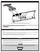
1. Verify mount orientation is correct (see nal assembly image on page 3 for reference).
2. Check fasteners and make sure they are tight and to proper torque.
3. Verify that plow blade can rotate freely without interfering with tires or vehicle body. If interference is found, it may be necessary
to adjust the location of the plow mount towards the front of the vehicle.
4. Verify maximum plow lift height to avoid damage to plow mount, push tubes and frame.
Once system check has been performed, you are ready to operate your plow system.