
Owners manual

©2013 Warn Industries, Inc. WARN® and the WARN logo are trademarks of Warn Industries Inc. 6 91853A0
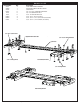
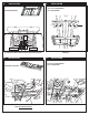
<24”
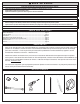
Figure 8: Place push tube bracket against the spine bracket and adjust until a set
of pin holes are less than 24 inches from the front of the forward facing tires.
Figure 9: Loosely fasten push tube bracket to spine bracket with carriage bolts and
locking nuts.
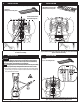
8. INSTALLATION 9. INSTALLATION
Pin Holes
(4) 3/8 - 16 x 3/4- Carriage Head Bolt
(4) 3/8 - 16 Locking Hex Nut
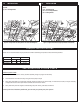
Figure 10: Slide adjustable rear contact plate onto spine plate to align with rear
u-bolts. Do not fasten at this time.
10. INSTALLATION 11. INSTALLATION
Figure 11: Loosely secure rear contact plate to spine with carriage bolts.
(2) 3/8 - 16 x 3/4- Carriage Head Bolt
(2) 3/8 - 16 Locking Hex Nut
(1) Push Tube Attach Bracket
(1) Adjustable rear contact plate
Pin Holes