
Owners manual

©2013 Warn Industries, Inc. WARN® and the WARN logo are trademarks of Warn Industries Inc. 5 91853A0
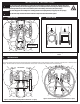
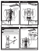
Figure 5: While centering spine plate, align with front u-bolts and mark skid plate
for clearance hole drilling.
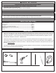
4. INSTALLATION
Figure 6: While centering rear contact plate, align with rear u-bolts and mark skid
plate for clearance hole drilling.
5. INSTALLATION
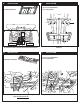
Figure 7: Drill skid plate for u-bolt clearance holes.
6. INSTALLATION
7. INSTALLATION
Figure 8: Insert front pair of u-bolts through skid plate clearance holes and spine
plate. Loosely attach front end of the spine plate to u-bolts.
WARNING
Always use extreme caution when drilling on any vehicle. Make sure
that all fuel lines, brake lines, electrical wires, and other objects are not punctured or
damaged when/if drilling on the vehicle. Failure to inspect the area to be drilled may
result in vehicle damage, electrical shock, re or personal injury.
NOTICE
Thoroughly inspect the area to be drilled (on both sides of material) prior to drilling,
and relocate any objects that may be damaged and then drill clearance holes for u-bolts.
NOTE: During operation, vibration may occur between skid plate and mount. Before installing
your plow mount, you may choose to add a sheet rubber isolator between skid plate and
mount, to eliminate excess vibration.
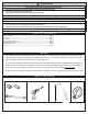
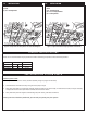
(2) U-bolts
(4) 5/16 - 18 Locking Hex Nut
NOTE: If skid plate is NOT present, skip to step 7.
(1) Adjustable Rear Contact Plate
(1) Grease pencil or center punch
(1) Spine Plate
(1) Grease pencil or center punch
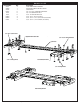
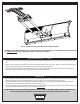
<19”
Front of spine plate less than
19 inches from the front of
the forward facing tires.