
User Manual


987606A1.doc Page 36 of 46
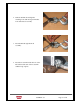
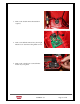
2.10.1 WIRING DETAILS
• Route Red Lead Wire from J3 Terminal on Circuit Board through Wire guides
up into handle to Trigger Switch.
• Route Red Lead Wire (soldered to Male Terminal Support) from J2 Terminal
on Circuit Board through Wire guides up to where the male Terminal support
is mounted.
• Route Black Lead Wire from J4 Terminal on Circuit Board through Wire
guides up to Trigger Switch.
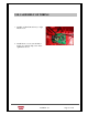
• Route the black lead attached to male terminal support to Rocker Switch.
• Route black lead attached to Black J4 lead at Trigger down through guides
and attach to Rocker Switch.
• Route Motor wires to top of Trigger Switch. Red lead to M+ terminal, black
lead to M - terminal.
• Use tie strap to secure Motor Wires to the right hand frame.
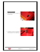
• Secure the Trigger Switch with switch Retainer and a screw. Secure the Wires
in the handle using wire retainer and screws.
• See Wiring diagram 75824 for installation Wiring schematic