
Owners manual

WARN® INDUSTRIES PAGE 5 88853 Rev A0
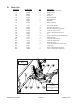
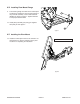
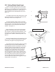
Figure 5
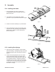
Figure 6
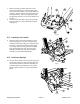
Figure 4
7. With the springs in position, pull back on the
push tube assembly (A1) until stop block plates
clear the rib mount plates. Secure stop block into
position to prevent springs from pulling push tube
assembly forward. Secure the stop blocks (A8)
by tightening fasteners. Do not torque fasteners at
this time.
8. Install fasteners (B5, B8) to push tube assembly.
Tighten fasteners to torque specications listed.
See gure 4.
IV.C. Installing Latch Handle
9. Rotate the base of the tube assembly to center
position aligning the rear slots of the push tube
assembly. Install spring (B14) over forward center
bolt head of push tube assembly. Install handle
over spring and into slot in push tube assembly.
Align latch handle pivot hole and secure with
fasteners (B2,B12,B15). See gure 5.Tighten
fasteners to torque specication listed.
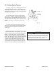
IV.D. Tensioning Springs
10. Use 3/8” drive ratchet to rotate spring hanger (A2)
and stretch plow spring. Align spring hanger with
the rst hole position in push tube assembly (A1)
and install fastener (B1,B2,B3) to secure spring
hanger. Tighten fasteners to torque specication
listed.