
Instructions / Assembly


20
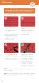
Step 5 -
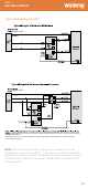
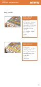
Layout Planning
• The standard (UL-Approved
minimum) spacing is 3 pegs
(3 /") between parallel
heating cables.
• DO NOT install parallel runs of
heating cable closer than 2"
if using cable fixing strips or 2
pegs (2 ") if using the
DCM-PRO membrane.
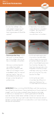
• The heating cable must not
be cut, shortened, extended
or le in a void, it must be fully
installed within the layer of
thinset or levelling compound.
• When installing the cable
DO NOT cross the cable over
another run, over coldtails
or the floor sensor. This will
cause overheating and will
damage the cable.
NOTE: The heater should not be installed on irregular surfaces such
as stairs or up walls.
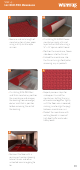
Before you begin
• Heating cables cannot be
installed across expansion
joints within the floor. Where
a heated floor is divided by
expansion joints, individual
cables should be used to
heat each area. The cold tail
may cross the expansion
joint within a 12” long UL/cUL
certified conduit if necessary.
A plan of the cable layout is required as part of the
control card so that any cutting or drilling aer tiling
will not result in injury or damage to the heater.
NOTE: Ensure the heating cable is at least 8" away from the influence
of other heat sources, such as heating and hot water pipes, lighting
fixtures or chimneys at all times.