
Instructions / Assembly
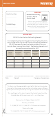

32
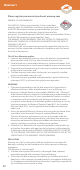
Install the thermostat in accordance with its installation
instructions
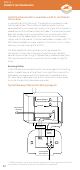
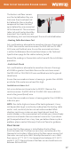
Typical Warmup Thermostat Wiring Diagram
Instructions for fitting Warmup® Thermostats can be found inside
the thermostat box. The UL/cUL certified thermostat must be
connected to the main electrical supply via a fuse or circuit breaker in
accordance with the National Electrical Code. If the thermostat used
does not include a built-in Ground Fault Circuit Interrupter (GFCI),
then one must be added to the circuit between the main power
supply and the thermostat. If the thermostat does include a GFCI, it is
NOT recommended to include another in the circuit, as this is likely
to cause nuisance tripping of the GFCI’s.
The total load of the heating cable(s) must not exceed the
thermostat’s limit or the amperage rating of the circuit or other
control switch without using an appropriately rated contactor/relay.
Warmup thermostats have a maximum resistive load rating of 15
Amps.
Ensuring Safety
Install the Warmup thermostat within the same room as the heating
cables. In order to ensure the eicient running of the system within
bathrooms, we recommend that the controls are located at least
60” away from shower openings or basin back splash areas so you
minimize the possibility of exposure to water.
* Undertile heaters are to be installed in parallel across the load terminals of the
thermostat or contactor and must not exceed their rated load.
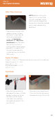
Step 9 -
Connect the Thermostat
L1-LOAD-L2
L1-LINE
L2
1
2 3
EXT
FLOOR SENSOR
(NO POLARITY)
BARE COPPER
(GROUND)
L1-LINE-L2
POWER
SUPPLY
L2-LINE-RED
L2-LOAD-RED
L1-LINE-BLACK
L1-LOAD-BLACK
Live (Hot)
Neutral (120V) or
Live (Hot) (240V)
L1-LOAD-L2
HEATING*