
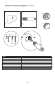
Specifications
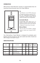


16
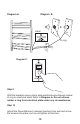
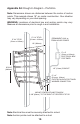
Appendix A2: Rough-In Diagram - Portofi no
Note: Dimensions shown are distances between the center of anchor
points. This example shows 16” on center construction. Your situation
may vary depending on your stud spacing.
W ARNING: Locations of electrical box and anchor points may vary.
Measure all dimensions prior to rough-in and installation.
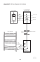
PERMANENT 120V ac
FROM HOUSE POWER
25 3/16”
(640mm)
MOUNT CENTER OFJUNCTION BOX
2 3/8” (60mm) TO THE RIGHT OF CENTER OF STUD
16” (406mm)
1/2” (13mm) CONDUIT
2” x 4”
(51mm x 102mm)
ELECTRICAL BOX
FOR TIMER
2” x 4”
(51mm x 102mm)
ELECTRICAL BOX FOR TOWEL
WARMER CONNECTION
2” X 4” STUD
(51mm x 102mm)
2” X 4” STUD
(51mm x 102mm)
Note: Electrical box must be securely attached to a stud.
Note: Anchor points must be attached to a stud.