IMPORTANT: BEFORE STARTING YOUR FLOOR WARMING PROJECT, PLEASE REVIEW THESE IMPORTANT DO’S AND DON’TS DON’T NEVER cut the warming cable NEVER shorten the warming mat NEVER connect TWO (2) or more warming mats together in series NEVER fold or position the warming cable so that it overlaps itself or other wires (this could cause dangerous overheating) NEVER run a power lead or sensor wire across the warming cable NEVER place built-in cabinets or other furniture with solid bases on top of the heated area of
SYSTEM INSTALLATION The installation process for a WarmlyYours floor warming system is similar to that of floor covering installation and is performed using many of the same tools. With a little care and conscientious observance of the installation instructions, a first time installer should have great success completing their floor warming project. If you encounter any difficulties while installing your system, installation support is available 24/7 by calling (800) 875-5285.
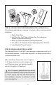
STEP 2: GATHER TOGETHER REQUIRED INSTALLATION TOOLS The following materials are required to perform a floor warming system installation: 1. Digital Ohm Meter 2. Hot Glue Gun, Duct Tape or Staple Gun (for holding the system in place while working) 3. Broad Tip Permanent Marker and Tape Measure 4. 1/4”, 3/8” or 1/2” Notched Trowel, Depending Upon Tile Size 5.
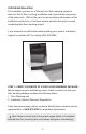
STEP 4: CHECK AND PREPARE THE SUBFLOOR WarmlyYours floor warming systems may be installed over any subfloor that is approved for tile or stone application, including plywood, backer board and concrete slabs. Note: While WarmlyYours systems provide up to 25% more heating power per square foot than the nearest competitor, the slab will always act as a “heat sink.” We suggest using Cerazorb® over a slab, between the cable and slab.
STEP 6: CHECK SYSTEM OHM READING PRIOR TO INSTALLING Before installing a system, check the Ohm resistance between the two (2) power conductor wires to make sure that no breaks or shorts have occurred that could affect the system’s future performance, and also test between the two (2) braided sheaths. The Ohm reading should be within +/- 15% variance of the factory reading indicated on the UL label attached to the warming mat.
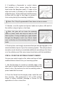
2. If installing a thermostat or control device that includes a floor sensor, place the sensor head under the fiberglass mesh, 6” inside of the edge and center it precisely in the middle of the serpentine loop. Once positioned, hold the sensor in place with hot glue or duct tape to prevent it from moving during the remaining installation. Note: The 7-Day Programmable Timer does not use a sensor. 3.
STEP 9: ELECTRICAL POWER HOOK-UP When required by local codes, use a licensed and qualified electrician to perform the system’s final electrical hook-up. Note: Always connect the system to a dedicated, GFCI protected, Circuit. STEP 10: SYSTEM OPERATION Before operating a new floor warming system, wait until the thinset cement used to lay the tile or stone floor has fully cured to the manufacturer’s specifications (usually 2 to 14 days).
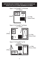
BATHROOM AND POWDER ROOM LAYOUT EXAMPLES WITH 3’x2’ & 3’x3’ FLOOR WARMING SYSTEMS Figure 1: 3’x2’ EasyMat™ in Toilet area 5’ 6” (168cm) 6’ (183cm) 3’ x 2’ Mat (91cm x 61cm) Figure 2: 3’x3’ EasyMat™ by Shower 7’ 2” (218cm) 5’ (152cm) 3’ x 3’ Mat (91cm x 91cm) Figure 3: 3’x3’ EasyMat™ by Tub 8’ (244cm) 3’ x 3’ Mat (91cm x 91cm) 5’ (152cm) 8
BATHROOM AND POWDER ROOM LAYOUT EXAMPLES WITH 3’x5’ & 3’x6’ FLOOR WARMING SYSTEMS Figure 4: 3’x 5’ EasyMat™ Tub and general coverage 8’ 9” (267) 6’3”’ (191cm) 3’ x 5’ Mat (91cm x 152cm) Figure 5: 3’x 6’ EasyMat™ by Shower and general coverage 9’ (274cm) 6’ (183cm) 3’ x 6’ Mat (91cm x 152cm) Figure 6: 3’x 6’ EasyMat™ by Shower and general coverage 9’ (274cm) 5’ 9” (175cm) 3’ x 6’ Mat (91cm x 183cm) 9
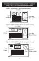
BATHROOM AND POWDER ROOM LAYOUT EXAMPLES WITH 3’x8’ & 3’x10’ FLOOR WARMING SYSTEMS Figure 7: 3’x 8’ EasyMat™ in Double Vanity area 15’ (457 cm) 3’ x 8’ Mat (91cm x 244cm) 15’ (457 cm) Figure 8: 3’x 10’ EasyMat™ by Shower and general coverage 13’ (396cm) 10’ (305cm) 3’ x 10’ Mat (91cm x 305cm) 10
RECORD YOUR SYSTEM’S OHM READINGS HERE FOR READY REFERENCE Four (4) Ohm readings should be taken from each mat at each stage of the floor warming system installation as listed below. This is necessary to ensure that your system is functioning properly and that no breaks or shorts have occurred that could affect its performance or integrity. 1. C ore to Core: This is the reading between the two inner conductors of the lead wires. 2.
When installed on top of a concrete slab without insulation, it is generally accepted that a radiant floor warming system will take the chill away from the floor and provide a small amount of warmth. Adding insulation on top of the slab and beneath any floor warming system will allow a greater percentage of the heat generated to transfer to the flooring surface. This leads to greater efficiency and therefore faster warm up times, higher expected surface temperatures and lower energy usage.
WARMLYYOURS FLOOR WARMING SYSTEM WARRANTY REGISTRATION Thank you for purchasing your new WarmlyYours floor warming system. To register your system, please send a copy to WarmlyYours via mail at 590 Telser Rd, Suite B Lake Zurich, IL 60047, FAX to (800) 408-1100, or scan and send via email to: WarrantyRegistration@warmlyyours.com within 30 days of date of purchase. 1. HOMEOWNER INFORMATION Name Phone Address Email City State Zip 2.
WARMLYYOURS FLOOR WARMING SYSTEM WARRANTY WarmlyYours, Inc.