
User guide

Installation and Operation
SECTION 5
5.5.2 Install the TempZone™ Floor Heating Cable (Twin)
1.Begininstallingtheheatingcablefromthethermostatorjunctionbox.Followthepatternmarkedontheoorplan(if
supplied).Pleasenotethethicknessofthefactoryspliceandcoldleadandplanaccordingly.
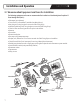
2.Unwindthecablefromthespool.SecureitusingtheTempZone™CableFixingStrips.Avoidbunchingthecableor
crossingoverotherpartsofthecable.
3.TheTempZone™FloorHeatingCable(Twin)shouldbeinstalledinauniformly-spacedserpentinepattern.Referto
either“ProductSelectionGuide--120V”or“ProductSelectionGuide--240V”insection9forspacinginformation.
4.Takenoteofthecable’shalfwaypointmarkingindicatedonthecable.Thismarkshouldmatchthehalfwaypoint
indicatedonthecustomSmartPlan™suppliedwiththeorder(optional).
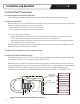
5.Routethepowerleadsfromtheoortothethermostatbox.Ifusingmultipleheatingcables,routethepowerleadsfrom
theoortoajunctionboxorthermostatboxinthewall.
NOTE: Leads should be protected at the point they leave the oor. Rigid metal conduit, intermediate metal
conduit, rigid nonmetallic conduit, electrical metallic tubing, or other means approved by local electrical codes
should be used.
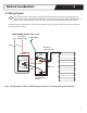
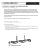
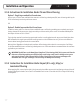
6.Forinstallationsincludingathermostat,thelow-voltageoorsensorshouldbeplaced
inbetweentheloopscreatedbythecableandheldinplacewithasmallamountof
thinsetorhotglue.SeeFigure7.
Thesensorwirecannotcrossanyheatingcableorleadwire.Itmustextendatleast6
inchesintotheheatedarea.Thesensoranditswireshouldbecovereddirectlywith
thinsetorself-levelingunderlayment.
Thecoldleadwiresshouldbeplacedabovethesuboor,alongthesideoftheheated
areaatleast2inchesfromtheheatingwire.Securethecoldleadwireswithasuitable
tapeorhotgluebeforethethinsetorself-levelingunderlaymentisappliedoverthe
cables.
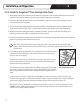
7.UseanohmmeterortheohmstestingfunctionofPowerMan™tocheckthecontinuity,insulationresistance,and
resistancevaluesagainafterthecablehasbeeninstalled.Comparethesepost-installationvalueswithpre-installation
valuestoensuretheyareconsistent.Recordpost-installationvaluesonthewarrantycardinsection10.
AttachCircuitCheck™orPowerMan™tocoldleadsatthistime.Refertosection5.3and5.4forinstructions.Setthe
PowerMan™tothe“OHMS”settingtocheckresistance.Aftercheckingresistancevalues,setthePowerMan™tothe
“CIRCUITCHECK”settingtobegininstallation.
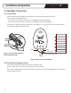
Figure 7. Placement of the
oor temperature sensor
15