
User guide

Free Design Service • 24/7 Installation Support • No Nonsense™ Warranty •(800) 875-5285 • www.WarmlyYours.com
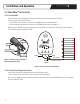
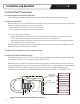
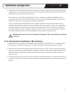
SHEATH
CORE
CORE
Black Inner Lead
Yellow (120V)
or Red (240V)
Inner Lead
Copper
Ground Sheath
ON OFF
BLACK
GREEN
RED
Wire Construction
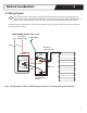
Circuit Check Installation
10061
Rev 1/11
BRAIDED GROUND SHEATH
COLD LEAD
BLACK WIRE
RED 240V
or
YELLOW 120V
Installation and Operation
SECTION 5
5.4 Circuit Check™ Instructions
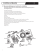
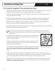
5.4.1 Install TempZone™ Floor Heating Cable (Twin)
InstalltheoorheatingcableinaccordancewiththedesignlayoutandinstructionsprovidedbyWarmlyYours.
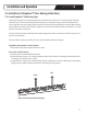
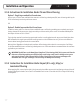
5.4.2 Test the Circuit Check™
Beforeconnectinganywires,installthebatteriesinthedeviceandturnitonandofftotestthealarm.Afterconrmingthat
thealarmisingoodworkingorder,connectthewiresasfollows:
•Connectblackinnerconductorcorewiretotheblackterminal
•Connectsecondinnerconductorcorewiretotheredterminal
Therearetwowaysofdoingthenextstep:
1.Splitthegroundsheathintwo.Connectonehalfofthegroundsheathtothegreenterminal,turnontheCircuit
Check™,andtouchtheotherhalfofthegroundsheathtooneoftheinnerconductorwires.
2.Installtheentiregroundintothegreenterminal.Turnonunitanduseapaperclipasabridgebetweentheground
wireandeitheroneoftheinnerconductors.
Eithermethodshouldactivatethealarm.IftheCircuitCheck™doesnotpassallthesetests,pleasecallWarmlyYours24/7
InstallationSupportat(800)875-5285forassistance.
5.4.3 Activate the Circuit Check™ and Proceed to Install Flooring
5.4.4 If the Circuit Check™ Alarm Sounds, Stop!
Ifthealarmsounds,thereisashortinthecircuitorbreakinthesystem.Refertothetroubleshootingguideinsection8of
thisinstallationmanualorcall24/7InstallationSupportat(800)875-5285.
WarmlyYourscanshipasplicekittorepairtheshort.Alternatively,thewiremayberepairedbyanelectrician.Pleasesee
thewirerepairdocuments“InstructionsforTwinConductorTempZone™Repair”atwww.warmlyyours.com/publications/TZ-
TWIN-REPAIR-30027-B/downloadand“TempZone™Cut&TurnTwinConductorSolderMethodWireRepair”at
www.warmlyyours.com/publications/TZ-TWIN-SOLDER-REPAIR-30028-A/downloadorcallus24/7at(800)875-5285.
13
Figure 5. How to connect the Circuit Check™ for installation