
User guide

11
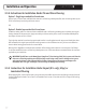
5.3 PowerMan™ Instructions
5.3.1 Test the Cable
InstallthebatteriesinthePowerMan™deviceandtesttheresistanceofeachsystemoutofthebox.
Testeachsystemindividuallythreetimes.
•ConnectrstinnerconductorcorewiretotheL1(OHMS)terminalofthePowerMan™
•ConnectsecondinnerconductorcorewiretotheL2(OHMS)terminalofthePowerMan™
Placeswitchinto“OHMS”positionandrecordvalue.Ifvalueexceeds-5/+10%at20ºC(68ºF),pleasecallWarmlyYours
24/7InstallationSupportat(800)875-5285.
5.3.2 Test the Floor Temperature Sensor
Installthelow-voltageoortemperaturesensorafterinstallingthecable.
ConnecttheoorsensorwirestotheL1andL2terminalsofthePowerMan™.
Placeswitchin“OHMS”position.Ifvaluesareoutsidetherangeof8to20kΩ,pleasecallWarmlyYours24/7Installation
Supportat(800)875-5285.
Installation and Operation
SECTION 5
Installation Support • No Nonsense™ Warranty •(800) 875-5285 • www.WarmlyYours.com
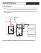
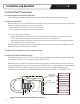
Wiring Tempzone to Power Man
Cold Lead Wire
From Warming System
Page 2
OHMS OHMS
CORE
CORE
GROUND
SHEATH
For
Single Conductor, Standard and Custom Mats
place the Power Man switch to
“CIRCUIT CHECK” and touch the ground sheath to one of the inner conductor wires.
For
Twin Conductor Mats
there are two ways of doing the next step:
• Split the ground sheath in two, connect one half of the ground sheath to the G terminal,
place the Power Man switch to “CIRCUIT CHECK” and touch the other half of the ground sheath
to one of the inner conductor wires.
• Install the entire ground into the G terminal. Place the Power Man switch to “CIRCUIT CHECK”
and use a paper clip as a bridge between the ground wire and either one of the inner conductors.
Either method should activate the alarm. If the Power Man does not pass all these tests,
please call WarmlyYours Customer Service at (800) 875-5285.
5. ACTIVATE THE CIRCUIT CHECK AND PROCEED TO INSTALL FLOORING
6. IF THE CIRCUIT CHECK ALARM SOUNDS, STOP!
The alarm sounding indicates a short in the circuit or break in the system. If alarm sounds, stop work
and install new batteries. If alarms continues, stop and check the troubleshooting guide in the
WarmlyYours installation manual or call 24/7 Installation Support at (800) 875-5285.
WarmlyYours can supply a splice kit to repair the short. Alternatively, the wire may be repaired by an electrician.
7. FINAL TEST
After tile and grout have been installed, test each system for ohms the third, and final time.
Record ohms values on the warranty card.
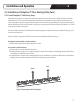
Ending Wire
2
From Warming System
Beginning Wire
1
From Warming System
OHMS OHMS
CORE
CORE
GROUND
SHEATH
SINGLE CONDUCTOR,
STANDARD AND CUSTOM MATS
1. “Beginning” wire is the lead wire from the start of the warming system roll.
2. “End” wire is the lead wire from the end of the warming system roll.
Notes:
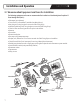
Power Man Installation for
TempZone™ Cut & Turn Roll (Single conductor)
TempZone™ Standard Mat (Single conductor)
TempZone™ Custom Fit Mat (Single conductor)
TempZone™ Cut & Turn Roll (TWIN Conductor)
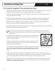
Figure 3. Structure of the TempZone™
Floor Heating Cable (Twin)
Figure 4. How to connect the PowerMan™
Installation Support • No Nonsense™ Warranty •(800) 875-5285 • www.WarmlyYours.com
Power Man Installation for
TempZone™ Cut & Turn Roll (Single conductor)
TempZone™ Standard Mat (Single conductor)
TempZone™ Custom Fit Mat (Single conductor)
TempZone™ Cut & Turn Roll (TWIN Conductor)
1. TEST ROLLS
Install the batteries in the device and test the resistance of each system out of the box.
Te st each system individually three times.
• Connect 1st inner conductor core wire to L1 (OHMS)
• Connect 2nd inner conductor core wire to L2 (OHMS)
Place switch into “OHMS” position & record value. If value exceeds +/-15%,
please call WarmlyYours.
2. LAY OUT THE WARMLYYOURS WARMING SYSTEM ROLL(S)
Lay out the roll(s) in accordance with the design layout and instructions provided
by WarmlyYours. Test resistance of each system a second time, see Install Manual.
Te st each system individually.
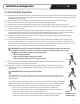
3. TEST THE FLOOR TEMPERATURE SENSOR
Install the floor temperature sensor after laying out the roll(s).
Connect the floor sensor wires to L1 & L2 terminals.
Place switch into “OHMS” position. If values are outside the range of 8-20 kOhms,
please call WarmlyYours.
4. TEST THE CIRCUIT CHECK
Move the switch to “CIRCUIT CHECK” to test the alarm before connecting any wires.
After confirming that the alarm is in good working order, turn off the unit and connect the wires
as follows:
• Connect 1st inner conductor core wire to L1 (OHMS)
• Connect 2nd inner conductor core wire to L2 (OHMS)
Please turn over to view detailed illustration
for wiring TempZone to the Power Man
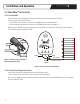
BRAIDED GROUND SHEATH
COLD LEAD
BLACK WIRE
RED (240V)
or
YELLOW (120V)
BRAIDED GROUND SHEATH
COLD LEAD
RED 240V
OR
WHITE 120V
BRAIDED GROUND SHEATH
COLD LEAD
TAPE INDICATORS
RED 240V OR
YELLOW 120V
Wire construction
TempZone Single
Conductor Mats
TempZone Standard
and Custom Fit Mats
BLACK
RETURN
WIRE
OUTER INSULATION LAYER
INNER
INSULATION
LAYER
TempZone™ Floor
Heating Cable (Twin)