
User guide

Installation and Operation
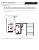
SECTION 5
10
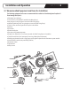
5.2 Pre-Installation Preparation
5.2.1Documenttheplan.FollowaSmartPlan™obtainedfromWarmlyYoursorprepareaoorplanoftheareatobeheated.Using
aoorplan,withtheTempZone™FloorHeatingCable(Twin)layoutmarked,makesiteasytotracetheheatingcablerouting
fortroubleshootingifnecessary.
5.2.2SelecttheappropriateTempZone™FloorHeatingCable(Twin),ensuringitisthecorrectlengthandvoltage.
5.2.3Identifyasuitablelocationforinstallingthethermostatandlow-voltagesensorifused.
5.2.4Markthelayoutoftheoorheatingcableontheoorplan.Takingphotographsoftheareamayalsobehelpful.
5.2.5InspecttheTempZone™FloorHeatingCable(Twin)visuallyandensurethatitisnotdamaged.Checkvoltage,wattage,and
resistancevaluesonthelabel.
5.2.6Propersurfacepreparationofoorisextremelyimportant.Makeabsolutelysurethattherearenoobjectsontheoor
thatmightdamagetheTempZone™FloorHeatingCable(Twin).Sweeptheoortoensureitiscompletelyclearofdebris,
includingnails,sharpmetallicobjects,wood,constructiondebris,anddamagedordefectivecables.
5.2.7Ifapplicable,installCeraZorb®ontheconcretesuboor.Followthemanufacturer’sinstructionswheninstallingthe
CeraZorb®insulatingunderlayment.
5.2.8CheckresistanceofTempZone™FloorHeatingCable(Twin)withanohmmeterorPowerMan™uponremovingitfrom
thepackage.Refertosection5.3forinstructionsonhowtoperformthetestingusinganohmmeterorPowerMan™.The
resistancevalueoftheheatingcableshouldmatchthevalueonthelabelattachedtothecablewithatoleranceof-5/+10%
allowedat20ºC(68ºF).Recordtheresistancevalueonthewarrantycardinsection10.
IMPORTANT:The electrical resistance of the cable must be checked before you begin and monitored
throughout the installation process to ensure there has been no damage causing shorts or breaks.
WarmlyYours recommends at least three readings be taken:
1. Before starting installation
2. After securing the cable in place on the suboor
3. After installing the ooring surface on top of the cable
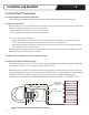
5.2.9UsinganohmmeterorPowerMan™,checktheinsulationresistanceofthecablebetweenthecorewires
andtothegroundwire.Itshouldalwaysreadinnity.
5.2.10UseaCircuitCheck™orPowerMan™deviceduringcableinstallation.Thesedeviceswillprovidean
audiblealarmifthewireisdamagedorcutduringinstallation.Acontinuitycheckerisnotacceptable
forthesetests
IMPORTANT: Beware of Using a Continuity Checker!
Forcablesthathaveover200Ωresistance,somecontinuitycheckersdonotsendenoughcurrentto
getcompletelythroughthewireandemitthenoiseorlightthatafrmspropercontinuity.Pleaseusea
digital ohmmeter.
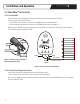
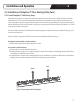
Three(3)ohmreadingsshouldbetakenforeachWarmlyYoursTempZone™FloorHeatingCableateach
stageoftheinstallationandrecordedinthetableonthewarrantycardinsection10.RefertoFigure2
forinstructionsabouthowtoattachtheohmmeterorPowerMan™totakeeachtypeofreading.
1.CoretoCore:Thisisthereadingbetweenthetwoinnerconductorsontheleadwires.
2.CoretoSheath,Yellow/RedLead:Thisisthereadingbetweentheinnercoreandtheouter
groundsheathontheleadwire.Thisreadingshouldbeinnity.
3.CoretoSheath,BlackLead:Thisisthereadingbetweentheinnercoreandtheouterground
sheathontheleadwireatthenishpointofthecable.Thisreadingshouldbeinnity.
Figure 2.
Attachment points
for ohm readings
Yellow
or Red
Ground
Ground
Yellow
or Red
Black
Black
Core to Core
Yellow
or Red
Ground
Ground
Yellow
or Red
Black
Black
Core to Sheath
Yellow
or Red
Ground
Ground
Yellow
or Red
Black
Black
Core to Sheath