
Instructions / Assembly
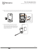

10. Make connections to line and load wires at the back of the thermostat. Place sensor wires into and through the
side vhole of the thermostat’s power base. Attach the sensor wires to the front of the thermostat’s power base.
11. Place the thermostat on the front of the white cover
plate and line up all of the holes. Use the included
screws to attach the power base and white cover plate.
Center and level the thermostat and then tighten the
screws to hold the pieces in place. Install thermostat’s
faceplate onto the power base.
Yellow(120V)
Red(240V)
Ground
Black
Sensor
Wire
ENT
Tube
PAGE 3 / 3
Installation Support • (800) 875-5285 • www.WarmlyYours.com
Floor Heating Application
Electrical Install Kit with Conduit Installation
BR1015A10b
© 2015 OJ Electronic A/S
C D
A B C D
out
in / sensor
LOAD
14
2
3
L1(L)
L2(N)
LINE
1800W/3600W MAX 15A
120/240VAC
LOAD
1
4
2
3
L1(L)
L2(N)
LINE
1800W/3600W MAX 15A
120/240VAC
BR1015A10b
© 2015 OJ Electronic A/S
A B C D
out
in / sensor