
Full Product Manual
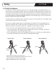
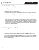

Figure 9. Attachment points for ohm readings
Testing
SECTION 6
6.4 Go by the Numbers
The resistance should be measured from the inner core of the yellow (120V) or red (240V) lead wire at one
end to the inner core of the black lead wire at the other end. Make sure that the probe of the ohmmeter does
not touch the tinned sheath wire at either end. Do not hold the wires onto the probes with your fingers. Even
your body’s electrical resistance can aect the reading if you touch the meter poles. A digital meter is easier
to use and strongly recommended. Verify that the batteries of the ohmmeter are good. Set your ohmmeter to
measure resistance in the range of 0 to 200 Ω.
For cables that have over 200 Ω resistance, it may be necessary to set the ohmmeter to the next higher range
of measurement to get an accurate ohm reading.
Three (3) ohm readings should be taken for each WarmlyYours TempZone™ Floor Heating Cable at each
stage of the installation and recorded in the table on the warranty card in section 10. Refer to Figure 9 for
instructions about how to attach the ohmmeter or PowerMan™ to take each type of reading.
1. Core to Core: This is the reading between the two inner conductors on the lead wires.
2. Core to Sheath, Yellow / Red Lead: This is the reading between the inner core and the outer ground
sheath on the lead wire. This reading should be infinity.
3. Core to Sheath, Black Lead: This is the reading between the inner core and the outer ground sheath on
the lead wire at the finish point of the cable. This reading should be infinity.
Yellow
or Red
Ground
Ground
Yellow
or Red
Black
Black
Yellow
or Red
Ground
Ground
Yellow
or Red
Black
Black
Yellow
or Red
Ground
Ground
Yellow
or Red
Black
Black
Core to Core Core to Ground Core to Ground
The ground wire may differ from the images above.
The ground wire may be represented as a additional wire with a stripe.
The testing procedure is still performed the same way.
19