
Full Product Manual

Installation and Operation
SECTION 5
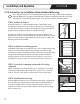
5.4.2 Install the TempZone™ Floor Heating Cable
1. Begin installing the heating cable from the thermostat or junction box. Follow the pattern marked on the
floor plan (if supplied). Please note the thickness of the factory splice and cold lead and plan accordingly.
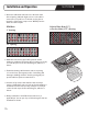
2. Unwind the cable from the spool. Secure it using the TempZone™ Cable Fixing Strips. Avoid bunching the
cable or crossing over other parts of the cable.
3. The TempZone™ Floor Heating Cable should be installed in a uniformly-spaced serpentine pattern. Refer
to either “Product Selection Guide--120V” or “Product Selection Guide--240V” in section 9 for spacing
information.
4. Take note of the cable’s halfway point marking indicated on the cable. This mark should match the halfway
point indicated on the custom SmartPlan™ supplied with the order (optional).
5. Route the power leads from the floor to the thermostat box. If using multiple heating cables, route the
power leads from the floor to a junction box or thermostat box in the wall.
NOTE: Leads should be protected at the point they leave the floor. Rigid metal conduit, intermediate
metal conduit, rigid nonmetallic conduit, electrical metallic tubing, or other means approved by local
electrical codes should be used.
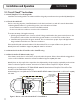
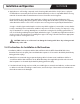
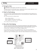
6. For installations including a thermostat, the low-voltage floor sensor should
be placed in between the loops created by the cable and held in place with a
small amount of thinset or hot glue. See Figure 7.
The sensor wire cannot cross any heating cable or lead wire. It must extend
at least 6 inches into the heated area. The sensor and its wire should be
covered directly with thinset or self-leveling underlayment.
The cold lead wires should be placed above the subfloor, along the side of the
heated area at least 2 inches from the heating wire. Secure the cold lead wires
with a suitable tape or hot glue before the thinset or self-leveling underlayment is applied over the cables.
7. Use an ohmmeter check the continuity, insulation resistance, and resistance values again after the cable
has been installed. Compare these post-installation values with pre-installation values to ensure they are
consistent. Record post-installation values on the warranty card in section 10.
Attach Circuit Check™ to cold leads at this time.
Figure 7. Placement of the
floor temperature sensor
13