
Full Product Manual


Electrical Considerations
SECTION 4
8
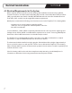
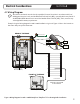
4.3 Wiring Diagram
Note: All electrical work must be done by a qualified, licensed electrician in accordance with local
building and electrical codes, and the National Electrical Code (NEC), especially Article 424, Part IX of
the NEC, ANSI/NFPA 70 and Section 62 of the Canadian Electrical Code (CEC), Part I, as well as any
other applicable statutory requirements.
Example of typical wiring diagram for 120V or 240V installations is given in Figure 1. Refer to the instructions
that came with your specific thermostat.
Figure 1. Wiring Diagram for 120V or 240V WarmlyYours TempZone™ Floor Heating Cable Installation
ENSURE THE SYSTEM
IS GROUNDED
HOUSE GROUND
BRAIDED GROUND SHEATH
COLD LEAD
BLACK WIRE
RED 240V
or
YELLOW 120V
REAR OF THE BASE
HOT (240V) or
NEUTRAL (120V)
HOT
FROM
POWER
SOURCE
FLOOR
FRONT OF THE BASE
FLOOR SENSOR
LOAD
14
2
3
L1(L)
L2(N)
LINE
1800W/3600W MAX 15A
120/240VAC
FROM
POWER
SOURCE
FLOOR
LOAD
1
4
2
3
L1(L)
L2(N)
LINE
1800W/3600W MAX 15A
120/240VAC
BR1015A10b
© 2015 OJ Electronic A/S
A B C D
out
in / sensor
in / sensor
A
B C
D
ou
t
in / sensor
in / sensor