
Installation Guide


7
buywarmall.com
The head part of the oor sensor must be installed directly between 2 wires. Use tape
or hot glue to x the sensor on the oor if your cables are installed with our plastic cable
guides.
The oor sensor and/or conduit must never
overlap a heating cable
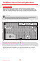
Cable and uncoupling membrane system
The oor sensor must be installed directly between two heating cables. Bend the wire and
x the tip of the oor sensor between two canes in the membrane and then pass the wire
between the cones all the way to the wall. The oor sensor must be installed to a minimum
of 16 inches inside the last heating cable. Do not cross the oor sensor cable with the heat-
ing cable. The oor sensor must not be installed near any other heat source other than the
heating cable. If the installation requires 2 oor sensors, install the 2nd between two rows of
heating cables.
Floor Sensor resistance measurement and installation
lnstall the oor sensor into the membrane (refer to drawing B).
Pass the cable in the wall to the thermostat. lt is possible to install conduit to pass the cable
inside to protect it. Refer to the oor sensor instruction guide which is with the thermostat
instruction guide.
The oor Sensor must be installed at least 16 inches from the walls to the interior of the
system heating. lt must also be installed directly between two rows of cables. Tape or
hot glue can be used to hold the oor sensor in place. One oor sensors is located in the
thermostat box and a second one in the cable box.
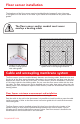
Floor sensor installation
A. Location of the probe in
the oor heating system
with cable guides
B. Location of the probe in the oor heating
system with an uncoupling membrane