
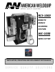
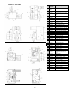
Specifications

5
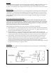
OPERATION
Robot Programming/Reamer Function
The cycle time for nozzle cleaning is controlled by the robot program.
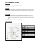
1) With the ground “ON” on Connection #4(See Fig 2), the clamp secures the welding nozzle in place, the
blade begins to rotate and the reamer spindle shaft starts its upward travel.
2) With the ground still applied, the reamer reaches the top of its stroke and remains there as long as the
ground is “ON”.
3) After the reaming cycle is completed program to turn the ground “OFF”. The reamer will then begin its
downward travel, continuing to rotate with the clamps still closed. Upon reaching the bottom of its stroke
(HOME position), the blade will stop rotating and the clamp will open.
4) Connection #2 is a “Cycle Status” which informs the robot of the clamping status. When the clamp is open
the robot will receive a 24VDC signal. The robot is now able to return to welding. NOTE: When the clamp
is closed during the cleaning cycle Connection #2 will read 0VDC. The robot program should not be
allowed any robot movements when Connection #2 is at 0VDC.
Robot Programming/Spray Function
The cycle time for the Spray function is controlled by the robot program.
1) The robot should be programmed by Connection #5 to spray after the reaming process while held in the
clamp. With the ground “ON” (Fig. 2) the sprayer will dispense anti-spatter solution until the ground is
turned “OFF”. Spray time should be determined by the robot operator/programmer.
2) The amount of anti-spatter delivered is controlled in two ways.
a) The length of time that Connection #5 is activated to ground “ON”.
b) Adjustment of the flow control valve located on the side of the unit directly above the anti-spatter
bottle.
3) Usual recommended spray time is .2 seconds to 1 second depending on the anti-spatter compound. Avoid
over saturating the nozzle.
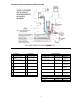
Feed Rate Adjustment
The feed rate “UP” and/or “DOWN can be controlled by adjusting the flow control valve located inside the unit.
Remove the rear cover for access to the valves. The top valve controls the speed in the “UP” direction. The
bottom valve controls the speed in the “DOWN” direction.
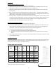
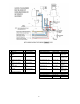
REAMER BLADE SELECTION CHART
PART #
NOZZLE
BORE SIZE
OD
ID
L1
L2
THREAD
TYPE
RB500
1/2”
(13mm)
.490”
(12.5mm)
.374”
(9.5mm)
2.56”
(44.7mm)
1.76”
(44.7mm)
Female –
3/8-24
RB560
9/16”
(15mm)
.555”
(14mm)
.435”
(11mm)
2.56”
(65mm)
1.76”
(44.7mm)
Female –
3/8-24
RB625
5/8”
(16mm)
.610”
(15.5mm)
.511”
(13mm)
2.69”
(68mm)
2.14”
(54mm)
Female –
3/8-24
RB625-01
5/8”
(16mm)
.610”
(15.5mm)
.453”
(11.5mm)
2.56”
(65mm)
1.76”
(44.7mm)
Female –
3/8-24
RB625-02
5/8”
(16mm)
.610”
(15.5mm)
.511”
(13mm)
2.95”
(75mm)
2.10”
(54mm)
Female –
3/8-24
RB625-03
5/8”
(16mm)
.590”
(15mm)
.433”
(11mm)
2.56”
(65mm)
1.76”
(44.7mm)
Female –
3/8-24
Other Reamer Blades Available Upon Request