DE Aufstell- und Bedienungsanleitung Pelletofen WP2-8A /WP2-8A K GB Installation and operating instructions Pellet Stove WP2-8 /WP2-8K FR Installation et instructions d’utilisation Chaudière à pellet WP2-8 /WP2-8K IT Istruzioni per uso e installazione WP2-8 /WP2-8K Stufa a pellet HU Kezelési- és használati útmutató Pelletkandalló WP2-8 / WP2-8K WP2-8 WP2-8K GRAN PELLET
WP2-8_D 2 / 192 Vielen Dank, dass Sie sich für unser Produkt entschieden haben. Bitte lesen Sie vor Aufstellung und Inbetriebnahme Ihres Gerätes die Anleitung! So vermeiden Sie Schäden, die durch unsachgemäße Installation oder Handhabung hervorgerufen werden können. Ihr Gerät wird Sie und die Umwelt lange mit einer optimalen Funktion verwöhnen.
WP2-8_D 3 / 192 1. WICHTIGE ALLGEMEINE HINWEISE Bei Installation und Betrieb dieser Feuerstätte sind alle Anleitungen des Herstellers, die europäischen Normen sowie die Vorschriften und Normen des Landes zu beachten, in dem der Ofen aufgestellt und betrieben wird. Sie vermeiden so Fehlfunktionen und Bedienfehler. Der Betreiber ist verpflichtet, sich vor Inbetriebnahme der Feuerstätte anhand der Anleitungen über die Besonderheiten der Feuerstätte und die geeigneten Brennstoffe zu informieren.
WP2-8_D 4 / 192 Die Reinigung der Feuerstätte muss regelmäßig durch den Betreiber erfolgen. Für die Wartung der Feuerstätte empfehlen wir den Abschluss eines Wartungsvertrages zwischen Fachhändler und Betreiber. Die regelmäßige Wartung kann auch durch den technisch versierten und vom Fachbetrieb fundiert eingewiesenen Betreiber stattfinden. Vor den Arbeiten Netzstecker ziehen! Der Netzstecker bzw. die zugehörige Steckdose muss jederzeit leicht zugänglich sein.
WP2-8_D 5 / 192 3. SYSTEMANFORDERUNGEN Unsere Geräte werden immer mit anderen bautechnischen Einrichtungen / Produkten verbunden und stellen daher, wie alle technischen Produkte, für den störungsfreien Betrieb bestimmte Systemanforderungen. Nachfolgend sollen einige besonders wichtige Anforderungen explizit genannt werden. Diese Aufstellung erhebt keinen Anspruch auf Vollständigkeit. Bitte beachten Sie alle Anleitungen / Angaben, wie bereits einleitend bemerkt.
WP2-8_D 6 / 192 zeige „INFO“) von einigen Minuten einprogrammiert, die abgelaufen sein sollte, bevor das Gerät neu gestartet wird. Bei Ansteuerung des Gerätes mit externem Regler sollte daher auf eine Mindestlaufzeit geachtet werden. Zu diesem Zweck ist in der Steuerung eine Nachlaufzeit einprogrammiert (einstellen über das Menü „INFO“).
WP2-8_D 7 / 192 PLUS oder Ö-Norm M7135) u.a. bei Aschegehalt, Schüttdichte, Zusammensetzung und Größe/Geometrie nicht zu vermeiden und führen zwangsweise zu Abweichungen bei verschiedenen Angaben. So bedeutet z.B. eine Verdoppelung des Aschegehalts von 0,25% auf 0,5% auch eine Verdoppelung der Reinigungs- und Wartungshäufigkeit. Nach DIN 51731 sind leider auch Pellets mit bis zu 1,5% Aschegehalt am Markt zulässig und verfügbar.
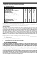
WP2-8_D 8 / 192 4. GERÄTE- UND FUNKTIONSBESCHREIBUNG 4.1. TECHNISCHE DATEN Max. Nennwärmeleistung Min. Nennwärmeleistung Brennstoffverbrauch (NWL / Teillast) ca. Wirkungsgrad (NWL) Wirkungsgrad (Teillast) Schonsteinzug (NWL / Teillast) Abgasmassensrom (NWL / Teillast) Abgasstutzentemperatur (NWL / Teillast) Inhalt Pellettank ca. Stromanschluss Frequenz Max. Leistungsaufnahme (Zündung) Min. Leistungsaufnahme Durchmesser Abgasstutzen Gewicht ca.
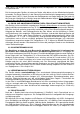
WP2-8_D 9 / 192 Am Ende der Heizgaszüge befindet sich ein Absauggebläse, das abgestimmt auf BrennstoffMenge und Verbrennungsluft, die Rauchgase sicher zum Schornstein führt. In regelmäßigen Abständen muss die Brennerschale durch den Betreiber von Asche und Schlacke gereinigt werden. Ebenso ist die Sichtscheibe vom Aschebelag zu reinigen. Zusätzlich ist eine regelmäßige Wartung der Heizgaszüge notwendig, die durch einen Fachbetrieb durchgeführt werden sollte.
WP2-8_D • 10 / 192 Alle Stahl- und Gussteile des Ofens wurden im Werk mit hochhitzebeständigem Lack beschichtet und eingebrannt. Beim ersten Anheizen des neuen Pelletofen trocknet der Lack nach, dabei kann Geruch und Rauch entstehen! Hierzu bitte folgende Ratschläge beachten: o Den Raum gut durchlüften, damit die freiwerdenden Dämpfe abziehen können. o Während der Aushärtezeit ist der Lack noch weich. Lackierte Flächen möglichst nicht berühren, um eine Beschädigung der Lackoberfläche auszuschließen.
WP2-8_D • • • • 11 / 192 Türe schließen. Gerät durch Drücken der I/O-Taste einschalten. Pellets werden in der Brennerschale gefördert. Das Anzünden erfolgt automatisch über die im Gerät eingebaute Zündung. Nach spätestens 5-10 Minuten beginnen die Pellets zu brennen. Schlägt die Zündung fehl (unverbrannte Pellets in der Brennerschale), prüfen Sie bitte zuerst die Brennerschale auf Verunreinigungen (alle Luftlöcher müssen frei sein) und ob der Vorratsbehälter aufgefüllt wurde.
WP2-8_D 12 / 192 Änderung der Temperatur Drücken der Taste P4 bis im Menü die Raumtemperatur angezeigt wird. Änderung der Werte mit den Tasten P5 oder P6 (Diese Menüeinstellung ist nicht verfügbar, wenn ein externes Thermostat aktiviert wurde). Der Zugang zur Schaltuhr Einstellung Drücken Sie die Taste P1 für ca. 5 sec.. HILFE –Taste (P3). Die Informationen werden durch Drücken der Taste P3 für ca. 10 sec. sichtbar gemacht. Für die ON / OFF Funktion halten Sie die Taste P2 für ca. 3 Sekunden gedrückt.
WP2-8_D 13 / 192 4.8. BENUTZER MENÜ Menüstruktur: Durch längeres drücken (ca. 3 Sekunden) der Taste P4 kommen Sie ins Benutzermenü. QUITTIEREN: VORFUELLEN: OFENSTATUS: PELLETSORTE-EINST.: RAUMGEBLÄSE-EINST.
WP2-8_D 14 / 192 4.9. ALLGEMEINE EINSTELLUNGEN Das Hauptmenü ist in zwei Seiten aufgeteilt, die mit den Tasten P5/P6 ausgewählt werden können: Erste Menüseite: QUITTIEREN: DATUM/UHRZEIT: DISPLAY OEKO: STAND-BY: FERNBED.
WP2-8_D 15 / 192 4.10. EINSTELLUNGEN HAUPTMENÜ DATUM / UHRZEIT Durch Anwahl und kurzes drücken der Taste P4 wechseln Sie in dieses Menü. Einstellung der Werte erfolgt über die Tasten P5 und P6. Eine Wochentag Einstellung ist nicht nötig. Durch längeres drücken der Taste P4 kommen Sie wieder zurück ins Menü. DISPLAY „OEKO“ Die Taste P4 aktiviert / deaktiviert den Anzeigemodus, nachdem nach 300 sec. keine Tasten mehr gedrückt wurde. Einstellung der Werte erfolgt über die Tasten P5 und P6.
WP2-8_D 16 / 192 Kommt diese Phase innerhalb der zugelassenen Zeitdauer von 1500 Sekunden nicht zustande, geht der Pelletofen wegen des Ausbleibens der Zündung in den Alarmstatus. BEDINGUNG DER STABILISIERUNG Nach Erreichen der min. Temperatur von 50°C schaltet die Zündung aus. Die vorgeschriebene Stabilität der Flamme und die Erhöhung der Temperatur mit mindestens 3°C/Minute müssen abgewartet werden. Die Zeitdauer dieses Zustands beträgt ca. 180 Sekunden.
WP2-8_D 17 / 192 Die L1 LED leuchtet 5.1. ERREICHUNG DES WERTES TEMPERATUR Der Pelletofen erhält kontinuierlich die gewünschte Temperatur und garantiert dem Benutzer die besten Bedingungen ohne große Leistungsschwankungen, mit einem minimalen Energieaufwand nach der Erreichung des Wertes. Die Leistung wird in einem Streifendiagramm angezeigt. Dieses Diagramm zeigt gleichzeitig auch die Raumtemperatur.
WP2-8_D 18 / 192 5.2. EINSTELLUNG DER SCHALTUHR Siehe untere Abbildung: Die Abbildung zeigt jeden Tag der Woche. Das Feld DAY (Tag) ist in 24 Perioden aufgeteilt, jede Periode dauert 1 Stunde (1, 2,….24) und ist wiederum in zwei Halbstunden aufgeteilt. Auswahl der Funktionen und der Stundenbereiche Durch das Drücken der Tasten P5 und P6 kann in beiden Richtungen unter den Symbolen (Stunden, Tage der Woche und den Symbolen der Programmierung „copy, add, exit“) gewählt werden.
WP2-8_D 19 / 192 Das Verfahren kann zu jeden Wochentag, zu dem Einstellungen kopiert werden, wiederholt werden. Zum Verlassen der Kopierfunktion mit den Taste P5 (vorwärts) oder P6 (zurück) zum Symbol exit gehen und wiederum die Tate P4 (SET) drücken. Im Beispiel Abbildung: Um 6:30 schaltet der Ofen im Niveau 3 (KOMFORT) ein. Um 12:00 schaltet der Ofen aus und bleibt in diesem Zustand bis 17:30. Um 17:30 schaltet der Ofen im Niveau 1 (ECO) ein.
WP2-8_D 20 / 192 Mit Hilfe der Schaltflächen P5-P6 stellen Sie das Gerät von ON(EIN) auf OFF(AUS). Zum Verlassen drücken Sie 2-mal die Schaltfläche P4. Danach erscheint im Hauptmenü die aktuell eingestellte Leistungsstufe: Zum Beispiel: X: die aktuelle Raumtemperatur ist 20,2’C Y: Der Ofen ist in der Leistungsstufe L1 eingestellt Einstellung der Leistungsstufe: Zum einstellen der Leistungsstufe drücken Sie die Schaltfläche P4.
WP2-8_D 21 / 192 X: Aktuelle Raumtemperatur Y: Eingestellte Raumtemperatur Die Raumtemperatur kann mit den Schaltflächen P5 und P6 eingestellt werden. Zurück zur Hauptseite gelangen Sie durch Drücken der Schaltfläche P4. 5.4. LEERUNG / AUFFÜLLUNG DES PELLETBEHÄLTER Der Pelletverbrauch des Ofens hängt von der eingestellten Leistungsstufe ab. Überprüfen Sie mindestens einmal täglich, ob die Menge ausreichend ist.
WP2-8_D 22 / 192 2. Danach erscheint auf dem Display folgender Text: 3. Jetzt drücken Sie sofort die Schaltfläche P1. Auf dem Display ist nun das „BEEP” ON (EIN) zu sehen: Zum Ausschalten von „BEEP” wiederholen Sie die drei vorgenannten Schritte. Danach ist auf dem Display zu sehen: 6. STAND-BY (ABSCHALTUNG) Nach Aktivierung des STAND-BY Modus und Erreichen der eingestellten Raumtemperatur (*) schaltet der Ofen aus und beharrt in diesem Modus.
WP2-8_D 23 / 192 (*) wenn die Raumtemperatur aktiv ist 6.1. OFEN SCHALTET AUS Sie können jederzeit das Gerät mit der Taste P2 (ON/OFF) ausschalten. Wenn der Ofen in den Ausschaltungszustand über geht, blinkt die grüne LED Lampe L2 bis zur vollen Abschaltung (OFF). AUSSCHALTUNGSZUSTÄNDE Nach dem Drücken der Taste P2 (ON/OFF) zum Ausschalten, geht der Ofen in den Zustand SWITCH OFF, danach in den Abkühlzustand über.
WP2-8_D 24 / 192 STROMAUSFALL Bei einem Stromausfall von kürzer als 10 sec. setzt der Ofen seinen Betrieb einfach wieder fort. Steht der Ofen im STAND-BY Modus wird dieser Zustand wieder hergestellt. In allen anderen Zuständen schaltet sich der Ofen bei einem Stromausfall aus.
WP2-8_D 25 / 192 Bei Beschädigung, schadhaften Stellen des Anschlusskabels ist dieses sofort zu tauschen. Zur Erneuerung eines Ersatzkabels nehmen Sie bitte den Kontakt mit unserem Kundendienst auf. 7.1. SICHERUNGSTAUSCH Achtung! Austausch darf nur von einem Fachmann ausgeführt werden! 1. STB Sicherheits-Temperaturschalter 2. Hauptschalter, Netzanschluss-Steckdose, Sicherungshalter 3. Temperaturfühler für Raumtemperatur 4.
WP2-8_D Die zwei Kabel des Thermostats schließen Sie am markierten Anschluss M10, Punkte 3,4 an. Einstellung des externen Thermostates in der Software: Drücken Sie die Taste P4 3Sec.
WP2-8_D 27 / 192 Mit der Taste P5/P6 wählen Sie das „HAUPTMENÜ“ aus und drücken nochmals die Taste P4. Mit den Tasten P5/P6 gehen Sie zur 2. Seite und wählen das Untermenü „EXTERNAL THERMOSTAT“ aus. Drücken Sie die Schaltfläche P4 um ins Menü zu gelangen. Mit Hilfe der Schaltflächen P5/P6 stellen Sie das Gerät von ON auf OFF. Exit : P4 8. REINIGUNG UND PFLEGE Bei der Verbrennung von Festbrennstoffen fällt immer Asche und Ruß an.
WP2-8_D 28 / 192 Achtung / Warnung: Brand-, Kurzschluss- und Lebensgefahr ! Der Betrieb der Geräte ist nur mit allen ordnungsgemäß montierten Verkleidungsteilen zulässig, da sonst die Zulassung der Geräte sowie Gewährleistung und Garantie erlöschen, weil die Gefahr besteht, Spannungsführende oder heiße Teile zu berühren.
WP2-8_D Reinigung des Brennertopfes Reinigen Sie den Brennertopf mit einem Staubsauger und bei Bedarf mit einer Bürste. Jede Öffnung muss frei von Rückständen sein. . Reinigung des Ascheraums Mit dem Staubsauger reinigen Sie den Ascheraum re./ li. und die Kanten der Brennraumtür.
WP2-8_D 30 / 192 Reinigung der Brennertopfhalterung Nach Herausnahme des Brennertopfes kann der Halterung von Rückständen befreit werden. Zum einsetzen des Brenntopfes achten Sie auf die richtige Position! 8.2. REINIGEN DER SICHTSCHEIBE Ein Scheibenbeschlag ist normal und stellt keinen Mangel dar.
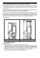
WP2-8_D 8.4. REINIGUNG DER HEIZGASZÜGE Demontage der oberen Abdeckung Die obere Verkleidung kann mit einer ruckartigen Bewegung nach oben abgezogen werden. Demontage des Strahlschutzbleches Nach dem Entfernen der zwei Flügelmuttern ist das Prallblech, schräg nach oben aus dem Ofenkörper zu nehmen.
WP2-8_D Demontage des Brennraumdeckels Nach dem Entfernen der zwei Flügelmuttern ist der Brennraumdeckel, schräg nach oben aus dem Ofenkörper zu nehmen. Achtung! Bei Wiedermontage achten Sie auf das richtige Nachziehen der Schrauben und auf die Unversehrtheit der Dichtungen! Undichtigkeiten können zu Betriebsstörungen führen! Entfernung des Umlenkbleches Nach der Reinigung des Umlenkbleches, kann dieses durch schräges Hochkippen aus dem Ofenkörper heraus genommen werden.
WP2-8_D Demontage des Reinigungsdeckels Unteres Verkleidungsteil entfernen. Danach die vier Schlüsselschrauben entfernen und den Deckel abnehmen. Achten Sie auf die Unversehrtheit der Dichtungen! Achtung! Bei Wiedermontage achten Sie auf das richtige Nachziehen der Schrauben und auf die Unversehrtheit der Dichtungen! Undichtigkeiten können zu Betriebsstörungen führen! Reinigung des Ascheraums Nach dem Aussaugen ziehen Sie den Aschekasten heraus.
WP2-8_D 34 / 192 Demontage der Wärmetauscher Die zwei Wärmetauscher (re/ li.) können durch leichtes wegdrücken der Luftleitbleche aus dem Ofenkörper herausgenommen werden. Reinigung der Wärmetauscher Saugen Sie die Abgasausgänge des Wärmetauschers mit einem Staubsauger aus und reinigen Sie evtl. Ablagerungen mit einer Reinigungsbürste. Loch muss auf der rechten Seite sein! Wichtiger Hinweis! Einmal in Jahr muss der Pelletbehälter gereinigt werden.
WP2-8_D 35 / 192 8.5. KONTROLLE DER LUFTANSAUGUNG Wenn eine externe Verbrennungsluftleitung an das Gerät angeschlossen ist, so sollte zunächst diese Leitung auf der gesamten Länge auf Verstopfungen optisch kontrolliert werden, damit sichergestellt ist, dass zum Luftansaugrohr des Gerätes überhaupt ausreichend Verbrennungsluft zugeführt werden kann. Etwaige Verstopfungen und Ablagerungen (z.B. Staubknäuel etc.) sind vollständig zu entfernen.
WP2-8_D 36 / 192 Bilder zur Erläuterung der Brandschutzabstände Beispiel mit Verbindungsstück zum Schornstein innerhalb des Aufstellraums Beispiel mit Verbindungsstück durch Wand zum Schornstein 9.1. EINRICHTUNGSGEGENSTÄNDE IM STRAHLUNGSBEREICH Im Sichtbereich (Strahlungsbereich) des Feuers muss zu brennbaren Bauteilen, Möbeln oder auch z.B. zu Dekostoffen ein Abstand von mindestens 100 cm (Maß A), gemessen ab Vorderkante Sichtscheibe, eingehalten werden.
WP2-8_D 37 / 192 9.5. ABSTÄNDE ZUM VERBINDUNGSSTÜCK (RAUCHROHR) Verbindungsstücke müssen am Gerät und untereinander fest und dicht verbunden sein. Sie dürfen nicht in den freien Schornsteinquerschnitt hineinragen. Das Verbindungsstück zwischen Ofen und Schornstein soll den gleichen Querschnitt haben wie der Rohrstutzen am Ofen. Waagerechte Verbindungsstücke über 0,5 m sollen zum Schornstein hin um 10 Grad ansteigen.
WP2-8_D 38 / 192 Stückholz oder andere Brenn- und Abfallstoffe dürfen niemals verwendet werden. Andere Brennstoffe führen auch zur Beschädigung und belasten unsere Umwelt. Wird der Ofen mit nicht zugelassenen Brennstoffen betrieben, erlöschen sämtliche Gewährleistungs- und Garantieansprüche und es können gefährliche Betriebszustände entstehen. Unternehmen Sie keine Experimente. Ein Pelletdurchmesser zwischen 5 und 7 mm ist zulässig. Die Durchschnittslänge der Pellets sollte 30-35 mm nicht überschreiten.
WP2-8_GB 39 / 192 Before installing and commissioning your appliance, please read these operating instructions carefully. In this way, you can avoid damage arising from unprofessional installation or operation. As a result, your appliance will safeguard the environment by operating in an optimal manner. WAMSLER Haus und Küchentechnik GmbH wishes you coziness and warmth, as well as plenty of hours to be spent with your pellet boiler.
WP2-8_GB 40 / 192 1. IMPORTANT GENERAL INSTRUCTIONS The installation and operation of the heating equipment shall comply with all the instructions of the manufacturer, the European standards and the standards of the country where the furnace is installed and operated. This is how malfunctioning and operating faults can be forestalled.
WP2-8_GB 41 / 192 The operator has to clean the combustion chamber regularly. To maintain the heating equipment, it is recommended to conclude a maintenance agreement between the specialized company and operator. The regular maintenance may also be performed by the operator having been thoroughly trained by the specialized company, under technically safe conditions. Before the commencement of works, the supply power cord shall be disconnected.
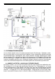
WP2-8_GB Sicherung fuse Schneckenmotor worm wheel engine Differenzdruckschalter differential pressure switch Raumluftventilator room air fan Abgasventilátor exhaust gas fan Kabelbaum cable harness Erde ground cable Nulle neutral cable Phase phase conductor Raumtemperature room temperatures Externe Thermostat….
WP2-8_GB 43 / 192 3. SYSTEM REQUIREMENTS Our appliances are always connected to other equipment / products of the construction industry, and therefore, as for all technical products, there are certain system requirements in connection with undisturbed operation. Hereunder, a few important requirements are specifically detailed. The list below has not been intended to be all inclusive. All the instructions / data mentioned above shall also be taken into consideration.
WP2-8_GB 44 / 192 3.4. SUPPLY OF THE COMBUSTION AIR The appliances operate as depending on the room temperature. Proper combustion air supply is absolutely necessary. There may not be any shortage of pressure in the room of installation. For this reason, in the case of combined installation and operation with air engineering equipment (for example, ventilation equipment, vapour exhausters, pneumatic conveyors, etc.
WP2-8_GB 45 / 192 3.6. CLEANING, MAINTENANCE AND CARE Unlike with liquid and gas fuels, solid fuels always generate ash and soot. The quality of combustion and handling comfort of pellet boilers are far better than those of similar boilers operated with shredded wood, yet the burning pan is to be cleaned (by the operator) with shorter intervals, while maintenance and checking become necessary less frequently in order to remove soot and ash from the equipment.
WP2-8_GB 46 / 192 4.2. SCOPE OF SUPPLY The scope of supply covers the following appliances: • Heat-resistant gloves, accessory tool to open the door, operating instructions. 4.3. DESCRIPTION OF THE OPERATION WAMSLER pellet boiler is a special heating equipment for household use, and is suitable for burning only 6 mm Ø wood pellet as described in Standard ENplus A1. The heating mode the equipment produces hot air, which radiated to the room.
WP2-8_GB 47 / 192 Cross-section of operation WP2-8A WP2-8KA (GRAN PELLET) with a convectional fan without a convectional fan 4.4. FIRST COMMISSIONING Important instructions: • Always keep the door of the combustion chamber closed, even when it is cold. • In heating made, all the surfaces can become extremely hot, especially the inspection windows, handles and control elements.
WP2-8_GB 48 / 192 Filling the supply tank Open the cover of the tank. Tear the seam of the pellet bag open, and with its opening looking downwards let the bag down to the screen grid, into the supply tank, and finally slowly discharge the contents of the bag into the tank. After filling, close the cover of the tank, which shall be always kept closed during operation. Our recommendation: Pour the pellet slowly into the tank from just a little height, because it would generate less dust.
WP2-8_GB 49 / 192 4.6. OPERATING AND HEATING MODE There are various keys to operate the appliance, completed by displays and indicators. In general, the appliance can be operated with the I/O key, as well as the "+" and "-" keys. P1 P2 P3 P4 P5 P6 L1 L2 status) A B Press to enter the timer menu.
WP2-8_GB 50 / 192 4.7. TEMPERATURE MENU The menu functions can be changed with the use of the P4 (SET / Menu) key. 1. 2. Current room temperature. Set room temperature. Use the P5 / P6 keys to increase or decrease the set temperature. Press the P4 key to acknowledge the set temperature. Press the P4 key again to return to the main menu. 4.8.
WP2-8_GB Raum T Einstellung Menue Set User Menue Service Menue key and Schaltuhr Einst. Quittieren Pelletzufuhr Offenstatus Pelletsorte-Einst. Raumgebläse-Einst. Hauptmenü Schaltuhr-aktiv Komforttemp. Normaltempl. Economytemp. Schaltzeitenprog. Datum/Uhrzeit Fernbed….. Sprachwahl Störungscode Wartung Foerderd. Menu Abgassensoreinst. Werkeinstell. Funtionstest Parametereinst.
WP2-8_GB 52 / 192 4.9. GENERAL SETTINGS The main menu has two sides, and you can move between them with the P5/P6 keys: First menu page: Quittieren: DATUM/UHRZEIT: DISPLAY DEKO: STAND-BY: FERNBED.
WP2-8_GB 53 / 192 4.10. SETTINGS MAIN MENU DATE / PRECISE TIME Enter this menu by pressing the P4 key shortly. These values can be set with the use of P5 and P6 keys. It is not necessary to set the weeks of the day. Return to the menu by pressing the P4 key longer. DISPLAY OFF The P4 key activates/inactivates the display mode in case no other key is pressed for 300 seconds. These values can be set with the use of P5 and P6 keys. STANDBY Select and press the P4 key shortly to enter this menu.
WP2-8_GB 54 / 192 Transmission to the next phase occurs only when the temperature of the exhaust gas rises over the smallest allowable value (50 °C). If this phase does not occur within the allowable 1500-second interval, the pellet boiler enters into alarm status due to the lack of ignition. STABILIZATION CONDITION After reaching the 50°C minimum temperature, the ignition switches off. One has to wait for the prescribed flame stability, and a temperature rise of at least 3°C/minute.
WP2-8_GB 55 / 192 The L1 LED is on. 5.1. REACHING THE TEMPERATURE (TEMPERATUR) VALUE The boiler consistently keeps the set temperature, and after reaching the set value it guarantees the best conditions for the users without major performance fluctuations and minimum energy consumption. Performance is presented on the screen by a band chart. This chart also indicates room temperature. SETTING THE TEMPERATURE The menu allows the setting of three temperature values: COMFORT, NORMAL, ECONOMY.
WP2-8_GB 56 / 192 5.2. SETTING THE TIMER See the graph below: The graph shows all the days of the week. The DAY field is split up into 24 periods, each of these periods lasts for 1 hour (1, 2, …. 24). Each of these hours is divided into two periods of 30 minutes. Selection of the functions and hour ranges By pressing the P5 and P6 keys, symbols can be reached in both directions (hours, days of the week, programming symbols of "copy, add, exit").
WP2-8_GB 57 / 192 Copying the settings of the day of the week: With the use of the P5 (next) or P6 (back) key, set the times, and then go to the copy symbol, press the P4 (SET) key to copy the settings. By pressing the P6 (back) key to return to the day of the week, and then press the P4 key select the day for copying the given values. With the use of the P5 (next) key, go to the Add symbol, and then press the P4 (SET) key.
WP2-8_GB With the use of the P5–P6 buttons, set switch from ON to OFF. To exit, press the P4 button twice. Now, the following main menu appears, showing the currently set performance grade: In the following example: X: The current room temperature is 20.2°C. Y: The fireplace operates at L1 heating performance. Adjustment of the performance grade: To enter the adjustment menu, press the P4 button.
WP2-8_GB 59 / 192 X: Current room temperature Y: Set room temperature The room temperature can be adjusted with the use of the P5 and P6 buttons. Return to the main page by repeatedly pressing the P4 button. 5.4. DISCHARGING/CHARGING THE PELLET TANK The pellet consumption of the fireplace depends on the set performance grade. Check at least once a day whether its quantity is sufficient. In case the tank is fully empty, then the "NoPellet" error message appears on the screen.
WP2-8_GB 60 / 192 3. Immediately push the P1 button, and the display shows that the "BEEP" has changed to ON: To disable the "BEEP", repeat the three steps, and then the following screen appears: 6. STAND-BY (SWITCHING OFF) After activating the STAND-BY mode and reaching the set room temperature (*), the switches off, and remains in this mode. Within 5 minutes, when the temperature exceeds the room temperature by 2°C, the boiler switches over to STAND-BY mode.
WP2-8_GB 61 / 192 When the boiler has been turned off, the green LED keeps flashing until it is fully switched off (OFF). INACTIVE STATUSES When the P2 (ON/OFF) key is pressed to turn the appliance off, the goes to SWITCH OFF status, and then switches over to cooling down. The exhaust gas fan switches to the highest grade in order to burn all the pellets in the combustion chamber. The following status can be reached only when the temperature of the exhaust gas does not exceed the 70°C limit value.
WP2-8_GB F01 no ignition F02 it is not stabilized 62 / 192 the pellet tank is empty, the quality of the fuel is not appropriate too little heat is generated after ignition F03 fail in exhaust temperature probe F04 fail in room temperature probe F05 too high temperature of the printed circuit board let the boiler cool down F06 exhaust pressure alarm (chimney blocked) chimney check F07 StB, too high internal temperature let the boiler cool down contaminated chimney / exhaust gas pipe / boiler, failed f
WP2-8_GB 7.1. FUSE REPLACEMENT Warning! The fuse may be replaced only by qualified personnel! 1. STB fuse – temperature switch 2. main switch, power supply socket, fuse holder 3. temperature sensor for room temperature 4. external thermostat, input The fuse may be replaced only in the case of boilers that have been disconnected from power supply! First, turn off the main switch, and then unplug the power cord from the power supply socket.
WP2-8_GB 64 / 192 stat into the designated M10 connector to terminal 3, 4. ENABLING THE EXTERNAL THERMOSTAT IN THE EXTERNAL SOFTWARE First keep the P4 button pressed (for 3 seconds). After pressing P4, the following menu is displayed: With the use of the P5–P6 buttons, choose the MAIN MENU, and press the P4 button again.
WP2-8_GB 65 / 192 With the use of the P5–P6 buttons, go to page 2, select and enter the “EXTERNAL THERMOSTAT (Y/N)” submenu by pressing the P4 button. With the use of the P5–P6 buttons, set switch from OFF to ON. To exit, press the P4 button. 8. CLEANING AND CARE The burning of solid fuels always generates soot and ash. Therefore, it is mandatory for the operator to clean the appliance regularly in order to ensure undisturbed operation.
WP2-8_F 66 / 192 Warning! / Important! Fire hazard, short-circuit risk and threats to life! The equipment may be operated only after all the intended covers have been fitted, otherwise the warranty and guarantee relating to the boiler become void, as there is a risk of contact with parts under voltage or hot elements! Before the commencement of works, unplug the electric supply connector, and re-plug it to the socket for the purpose of trial operation only when all the covers have been fully and professio
WP2-8_F Cleaning the burner pan Use a vacuum cleaner to clean the burner pan, and use a brush as required. Leave all the openings unobstructed, and free from residues. Cleaning the ash compartment Use a vacuum cleaner to clean the right/left ash space, as well as the edges of the door of the combustion chamber.
WP2-8_F 68 / 192 Cleaning the burner pan holder After removing the burner pan, the holder can be cleaned from deposits. When the burner pan is installed, pay attention to its proper position! 8.2. CLEANING THE INSPECTION WINDOW The appearance of vapour on the inspection window is a normal phenomenon, and does not indicate any deficiency. When solid fuels are used, deposition appears on the inspection hole, especially when the ash of the applied wood pellet is very fine.
WP2-8_F 8.5. CLEANING THE HOT GAS PASSAGES Dismounting the upper cover Pull the upper cover upwards with an abrupt motion. Dismounting the anti-radiation screen After removing the two butterfly nuts, the stop plate can be lifted out from the boiler body by pulling it upwards at an angle.
WP2-8_F Dismounting the cover of the combustion chamber After removing the two butterfly nuts, the cover of the combustion chamber can be lifted out from the boiler body by pulling it upwards at an angle.
WP2-8_F Dismounting the cleaning cover Remove the lower cover section. Then, remove the four screws, and lift the cover. Keep the gaskets undamaged! Warning! When resetting these elements, pay proper attention to the appropriate tightness of the screws and the undamaged nature of the gaskets! The lack of adequate tightness may cause malfunctioning! Cleaning the ash compartment Pull out the ash tray after exhausting the ash.
WP2-8_F Dismounting the heat exchangers Simply lift the two (right / left) heat exchangers to remove them from the boiler body. Cleaning the heat exchangers Vacuum clean the exhaust gas passages of the heat exchangers, and brush any deposits off them. Watch the bore hole to the right! Warning! / Important! Give the pellet tank a good turnout at least once per year.
WP2-8_F 73 / 192 Re-assemble the boiler in a reversed order! Pay attention to the undamaged nature of the gaskets, and correct assembly! 8.6. CHECKING THE AIR INLET When an external combustion air line is connected to the boiler, then first inspect this line all along its length to see whether it is clogged. It is suitable for ensuring whether the boiler receives sufficient combustion air. All clogging and deposited materials (for instance, accumulated dust, etc.) have to be fully removed.
WP2-8_F 74 / 192 Figures for the interpretation of fire protection distances Example with a connecting profile to the chimney, beyond the room of installation Example with a connecting profile via the wall to the chimney 9.1. FIXTURES IN THE RADIATION RANGE In the radiation range of the fire, the minimally 100 cm distance (size "A") of combustible building parts, furniture or for instance ornamental elements has to be kept from the front edge of the control window.
WP2-8_F 75 / 192 9.5. DISTANCES FROM THE CONNECTING PROFILES (FLUE) The connecting profiles have to be connected to each other and the boiler in a massive and tights manner. They may not protrude into the unobstructed cross-section of the chimney. The connecting profile between the boiler and chimney shall have the same cross-section as the pipe stub on the boiler. Connecting profiles that are longer than 0.5 meter shall rise above the chimney by 10 degrees.
WP2-8_F 76 / 192 Never use any shredded wood or other fuels, waste materials. Other fuels may cause harms and loading to the environment. If the boiler is operated with unpermitted fuels, then all the warranty and guarantee demands will become invalid, and hazardous operating conditions may occur. Do not experiment with the fuels! The allowable diameter of the pellet is in the range from 5 to 7 mm. The average length of the pellets should not exceed 30–35 mm.
WP2-8_F 77 / 192 Nous vous remercions d’avoir choisi notre produit. Avant l’installation et la mise en service de l’appareil, il est important de lire les instructions d’utilisation pour prévenir les dommages provenant du montage et de l’utilisation incompétente. Ainsi, votre appareil pourrait fonctionner pendant longtemps et de manière écologique. Nous vous souhaitons des heures agréables et du la chaleur assurée par notre chaudière à pellet la société WAMSLER Haus und Küchentechnik GmbH.
WP2-8_F 78 / 192 1. INSTRUCTIONS GÉNÉRALES IMPORTANTES Au cours de l’installation et du fonctionnement de la chaudière, il faut respecter les instructions du producteur, les prescriptions des normes européennes et les normes des pays où l’équipement est installé et utilisé, pour prévenir le fonctionnement défectueux et les problèmes de fonctionnement.
WP2-8_F 79 / 192 des nettoyages et des travaux d’entretien entraînent la cessation de la garantie. Avant la mise en service, il faut vérifier que tous les accessoires ont été sortis de la chambre de combustion et de la chambre de cendres et que le réservoir de pellet est exempt de résidu. L’utilisateur doit régulièrement nettoyer la chambre de combustion. Il est recommandé de signer un contrat d’entretien avec une société spécialisée.
WP2-8_F Sicherung fusible Schneckenmotor moteur Auger Differenzdruckschalter interrupteur de différence de pression Raumluftventilator ventilateur d’air ambient Abgasventilátor ventilateur de gas évacué Kabelbaum faisceau de câbles Erde câble de terre Nulle câble neutre Phase câble de phase Raumtemperature températures ambientes Externe Thermostat….
WP2-8_F 81 / 192 3. CONDITIONS DE SYSTÈME Comme nos appareils sont toujours utilisés avec d’autres équipements et produits de construction, il est important de respecter les conditions de système pour le fonctionnement correct. Dans ce qui suit, nous allons présenter quelques exigences concrètes, mais l’énumération n’est pas exhaustive. Il faut respecter toutes les instruction et données ci-dessus indiquées.
WP2-8_F 82 / 192 3.4. APPROVISIONNEMENT EN AIR DE COMBUSTION L’appareil fonctionne avec l’air du local. Il est donc particulièrement important d’assurer l’approvisonnement en air de combustion. Dans le local d’installation, il ne peut pas avoir de manque de pression.
WP2-8_F 83 / 192 3.6. NETTOYAGE, ENTRETIEN ET PROTECTION A la différence des combustibles liquides et du gas, les combustibles solides produisent toujours des cendres et de la scorie. La qualité de combustion et le confort d’utilisation des chaudières à pellet sont largement supérieurs à ceux des chaudières à bois coupé, mais la fréquence de nettoyage de la chambre à combustion est plus grande et il faut faire l’entretien et le contrôle plus fréquemment pour éliminer les cendres et la suie.
WP2-8_F 84 / 192 4.2. CONTENU DE LA LIVRAISON La livraison inclut les accessoires suivants: • Gants de protection contre la chaleur, outil pour l’ouverture de porte, manuel d’instructions. 4.3. DESCRIPTION DU FONCTIONNEMENT La chaudière à pellet WAMSLER est un équipement de chauffage spéciale pour l’utilisation domestique fonctionnant avec des pellets à diamètre de 6 mm, selon la norme Enplus A1. En mode de fonctionnement de chauffage, l’équipement produit de l’air chaud.
WP2-8_F 85 / 192 Vue de fonctionnement WP2-8A WP2-8KA (GRAN PELLET) avec un compression de convention sans compression de convention 4.4. PREMIÈRE MISE EN SERVICE Instructions importantes: • Il faut toujours garder fermée la porte de la chambre à combustion, même quand la chaudière est froide. • Pendant le mode de fonctionnement de chauffage, toutes les surfaces, en particulier la fenêtre de contrôle, les manches et les éléments de commande peuvent devenir très chauds.
WP2-8_F 86 / 192 Remplir le réservoir Ouvrir le couvercle du réservoir. Ouvrir le sec de granulés, mettre l’ouverture du sac dans le réservoir jusqu’à la grille de protection et le vider. Fermer le couvercle du réservoir et le garder fermé pendant le fonctionnement. Proposition: Verser le pellet lentement, d’une distance pas trop grande pour éviter la poussière. On peut remplir le réservoir à l’aide d’un seau ou d’autre moyen pareil.
WP2-8_F 87 / 192 4.6. COMMANDE ET MODE DE FONCTIONNEMENT DE CHAUFFAGE Il y plusieurs boutons pour la commande de l’appareil avec des messages affichés. Pour le fonctionnement de l’appareil, il suffit d’utiliser les boutons I/O et „+“ /„-“.
WP2-8_F 88 / 192 4.7. MENU TEMPÉRATURE Les fonctions peuvent être changées avec le bouton P4 (SET / Menu). 1. 2. Température ambiente actuelle. Températeur ambiente réglée. Avec les boutons P5 / P6 on peut augmenter ou réduire la température réglée. Pour accepter la température réglée, utiliser le bouton P4. En appuyant de nouveu sur le bouton P4, on peut retourner dans le menu principal. 4.8.
WP2-8_F Raum T Einstellung Menue Set User Menue Service Menue key and Schaltuhr Einst. Quittieren Pelletzufuhr Offenstatus Pelletsorte-Einst. Raumgebläse-Einst. Hauptmenü Schaltuhr-aktiv Komforttemp. Normaltempl. Economytemp. Schaltzeitenprog. Datum/Uhrzeit Fernbed….. Sprachwahl Störungscode Wartung Foerderd. Menu Abgassensoreinst. Werkeinstell. Funtionstest Parametereinst.
WP2-8_F 90 / 192 4.9. REGLAGE GÉNÉRAL Le menu principal est divisé en deux parties, entre lesquelles on peut se déplacer avec les boutons P5/P6: Première partie du menu: Quittieren: DATUM/UHRZEIT: DISPLAY DEKO: STAND-BY: FERNBED.
WP2-8_F 91 / 192 4.10. MENU PRINCIPAL RÉGLAGES DATE / HEURES On peut entrer dans le menu, en appuyant sur le bouton P4. Les valeurs peuvent être réglées avec les boutons P5 et P6. Il ne faut pas régler les jours de la semaine. Pour retourner au menu, il faut appuyer longuement le bouton P4. DISPLAY OFF (DESACTIVER L’ECRAN) Le bouton P4 active/désactive le mode de visualisation, si pendant 300 secondes, aucun bouton n’est appuyé. Les valeurs peuvent être réglées avec les boutons P5 et P6.
WP2-8_F 92 / 192 CONDITION DE STABILISATION Après l’obtenion de la température minimale de 50°C, l’allumage s’éteint. Il faut attendre la stabilité de flamme prescrite et l’augmentation de température de 3°C/minute. Cet état dure 180 secondes. Si cette condition n’est pas satisfaite, la chaudière à pellet entre dans le statut d’allarme à cause de la flamme irrégulière. CONDITION DE FONCTIONNEMENT A la température de 90°C du gas évacué, la chaudière allume le ventilateur.
WP2-8_F 93 / 192 Le LED L1 est allumé. 1.1. ARRIVÉE À LA VALEUR TEMPERATURE La chaudière maintient la température réglée et après son obtention, elle garantit les meilleures conditions pour l’utilisateur sans variations de puissances trop importantes, avec une consommation minimale d’énergie. Sur l’écran, la puissance est visualisée sous forme de diagramme. Il indique en même temps la température ambiante. REGLAGE DE LA TEMPERATURE Le menu permet de régler trois température: COMFORT, NORMAL, ECONOMY.
WP2-8_F 94 / 192 1.2. REGLAGE DU MINUTEUR A voir la figure suivante: La figure montre les jours de la semaine. La rubrique DAY (jour) est divisée en 24 périodes, une période dure une heure (1,2,….24). Les heures sont divisées en deux demi-heures. Choix des fonctions et des planches d’heures En appuyant sur les boutons P5 et P6, on peut se déplacer dans les deux direction sous les symboles (heures, jours de la semaine, symbole de programmation „copy, add, exit“).
WP2-8_F 95 / 192 En appuyant sur le bouton P6 (retour), on peut retourner aux jours de la semaine et en s’appuyant sur le bouton P4, choisir le jour où on veut copier les valeurs. Avec le bouton P5 (avant), il faut passer au symbole Add et appuyer sur le bouton P4 (SET). Cette opération peut être répétée pour chaque jour de la semaine où on veut copier les réglages.
WP2-8_F A l’aide des boutons P5-P6, passer du mode ON (activé) au mode OFF (désactivé). Pour sortir, appuyer deux fois sur le bouton P4. Vous verrez le menu principal suivant, avec la puissance réglée: Dans l’exemple suivant: X: La température ambiante est de 20,2°C Y: La chaudière fonctionne à la puissance de chauffage L1 Comment régler la puissance de chauffage? Pour entrer dans le menu de réglage, appuyer sur le bouton P4.
WP2-8_F X: Température ambiante actuelle Y: Température ambiante réglée 97 / 192 La température ambiante peut être réglée avec les boutons P5 et P6. Pour retourner à la page principale, il faut appuyer de nouveau sur le bouton P4. 1.4. VIDER /REMPLIR LE RESERVOIR DE PELLETS La consommation de pellets de la chaudière dépend de la puissance réglée. Il faut contrôler la quantité au moins une fois par jour. Si le réservoir se vide complètement, sur l’écran apparaît le message d’erreur „NoPellet”.
WP2-8_F 98 / 192 1. Sur l’écran principal, appuyer longuement (3 sec) sur le bouton P3. 2. Vous verrez sur l’écran l’inscription suivante: 3. Appuyer tout de suite sur le bouton P1, sur l’écran le „BEEP” passe à ON: Pour désactiver „BEEP”, il faut répéter ces trois opérations, et vous verrez l’écran suivant: 2. STAND-BY (DÉSACTIVATION) Après l’activation du mode de fonctionnement STAND-BY et l’obtention de la valeur réglée (*), la chaudière s’éteint et reste dans ce mode de fonctionnement.
WP2-8_F 99 / 192 (*) quand la température ambiente est active. 2.1. CHAUDIÈRE ÉTEINTE On peut éteindre la chaudière à n’importe quel moment avec le bouton P2 (ON/OFF). Quand on éteint la chaudière, le LED vert flash jusqu’à l’arrêt complet; ETAT ETEINT Quand on appuye sur le bouton P2 (ON/OFF), la chaudière passe à l’état SWITCH OFF et après, à l’état de refroidissement. Le ventilateur de gas évacué passe à une plus grande puissance pour que tous les granulés brûlent.
WP2-8_F F01 il n’y a pas d‘allumage F02 la stabilisation ne se produit pas 100 / 192 le réservoir à pellet est vide, la qualité du combustible est mauvaise après l’allumage, il se produit peu de chaleur F03 défaut de la température gas F04 défaut de la température ambiente F05 la température du circuit imprimé est trop élevée il y a une trop grande différence de pression entre le F06 gas évacué et l’air du local F07 StB, température internet trop élevée F08 ventilateur de gas évacué il faut laisser refro
WP2-8_F 101 / 192 3.1. RECHANGE DE FUSIBLE Attention! L’opération est réservée à des spécialistes. 1. STB fusible – interrupteur de température 2. interrupteur principal, prise de courant, portefusibles 3. senseur de température ambiente 4. thermostate externe, entrée Au moment de la rechange de fusible, la chaudière doit être sans tension. Il faut d’abord fermer l’interrupteur principal, après tirer le câble de la prise de courant.
WP2-8_F 102 / 192 Raccorder les deux câbles du thermostat aux prises M10 indiquées, aux points 3,4 AUTORISATION DU THERMOSTAT EXTERNE DANS LE LOGICIEL Tenir appuyé longuement (3 sec) le bouton P4. Après avoir appuyé sur P4, vous verrez le menu suivant: A l’aide des boutons P5-P6, choisissez le MENU PRINCIPAL et appuyez de nouveau sur le bouton P4.
WP2-8_F 103 / 192 A l’aide des boutons P5-P6, allez à la page 2, choisissez le sous-menu „THERMOSTAT EXTERNE (O/N)” et entrez en appuyant sur le bouton P4. A l’aide des boutons P5-P6, passez du NON à OUI. Pour sortir, appuyez sur le bouton P4. 8 NETTOYAGE ET PROTECTION La combustion des combustibles solides produit toujours des cendres et de la suie. Il est donc indispensable que l’utilisateur effectue régulièrement le nettoyage de l’équipement pour le fonctionnement sans anomalie.
WP2-8_F 104 / 192 Attention! / Important! Danger d’incendie, danger de court circuit, danger de vie! L’appareil doit être utilisé avec tous les revêtements prescrits pour la destination, autrement la garantie cesse à cause du danger de contact avec les pièces de rechange chaude ou sous tension. Avant de faire des travaux, il faut tirer le câble de l’appareil de la prise de courant. Pour le fonctionnement de test, tous les revêtements doivent être remonter sur l’appareil, avant sa mise sous tension.
WP2-8_F 105 / 192 Nettoyage du pot de combustion Nettoyer le pot de combustion avec l’aspirateur, en cas de besoin, utiliser une brosse. Toutes les ouvertures doivent être libres, exemptes de résidus. Nettoyage de la chambre à cendres Nettoyer avec un aspirateur les chambres à cendres droite et gauche, ainsi que les bords de la porte de la chambre à combustion. Il faut faire attention à ne endommager les joints de la porte.
WP2-8_F 106 / 192 8.3 NETTOYAGE DE LA FENÊTRE DE CONTRÔLE La formation de vapeur sur la fenêtre de contrôle est un phénomène normal et n’indique pas de problème de fonctionnement. En cas d’utilisation de combustibles solides, sur la fenêtre de contrôle se dépose une couche de cendre très fine. En fonction de la qualité des granulés (surtout en cas de petite puissance), ce dépôt peut être de couleur claire ou obscure.
WP2-8_F 8.5 NETTOYAGE DES CONDUITES DE GAS CHAUD Démontage du couvercle supérieur D’un geste brusque, il faut tirer le couvercle supérieur vers le haut. Démontage de la plaque de protection contre la radiation Après l’élimination des deux écrous, il faut tirer vers le haut la plaque et la faire sortir du corps de la chaudière.
WP2-8_F 108 / 192 Démontage du couvercle de la chambre à combustion Après l’élimination des deux écrous, il faut tirer vers le haut le couvercle de la chambre à combustion et la faire sortir du corps de la chaudière. Attention! Au montage, il faut bien serrer les vis et éviter l’endommagement des joints. Les joints endommagés peuvent causer des problèmes de fonctionnement.
WP2-8_F Démontage du couvercle de nettoyage Il faut éliminer le couvercle inférieur. Après prendre les quatre vis et enlever le couvercle. Il faut éviter les endommagements des joints. Attention! Au montage, il faut bien serrer les vis et éviter l’endommagement des joints. Les joints endommagés peuvent causer des problèmes de fonctionnement. Nettoyage de la chambre de cendres Après avoir aspirer les cendres, tirer le plateau de cendres.
WP2-8_F Rechange des échangeurs de chaleur Il faut tout simplement lever les deux échangeurs de chaleur (droit / gauche) et les faire sortir du corps de la chaudière. Nettoyage des échangeurs de chaleur Il faut nettoyer les conduites de gas des échangeurs de chaleur avec un aspirateur, ou les nettoyer avec une brosse, en cas de besoin. Alésage du côté droit! Attention! / Important! Une fois annuallement le stockage des granulés doit étre nettoyer. Si non, peut étre dysfunctionnement.
WP2-8_F 111 / 192 8.6 CONTRÔLE D’ASPIRATION D’AIR Quand une conduite d’air externe est raccordée à la cheminée, il faut commencer la révision avec cette conduite, de toute sa longueur, pour chercher des colmatages. Il faut vérifier si la chaudière reçoit suffisamment d’air pour la combustion. Il faut éliminer tous les colmatages et dépôts (poussières, etc). La fin des conduites d’air de combustion doit être posée hors de l’édifice, protégé du vent.
WP2-8_F 112 / 192 Figures pour l’interprétation des distances de protection contre l’incendie Exemple avec profil de connection à la cheminée, hors du local d’installation Exemple avec profil de connection à la cheminée, à travers le mur 9.2 MOBILIERS DANS L’AIRE DE RADIATION Dans l’aire de radiation du feu, il faut respecter la distance de 100 cm par rapport à des parties d’édifice, meubles ou objets de décoration inflammables (dimension „A”), à calculer du bord frontal de la fenêtre de contrôle.
WP2-8_F 113 / 192 9.6 DISTANCES PAR RAPPORT AUX PROFILS DE CONNECTION (CONDUITE DE FUMÉE) Il faut bien raccorder les profils de connection entre eux et à la cheminée. Ils ne peuvent pas entrer dans la partiel libre de la cheminée. Le profil de connection entre la chaudière et la cheminée doit avoir le même diamètre que la conduite sur la chaudière. Les profils de connection de plus de 0,5 m doivent se lever de 10 degrés sur la cheminée.
WP2-8_F 114 / 192 La longueur moyenne des granuls doit rester entre les valeurs 30 - 35 mm. Il est également interdit d’utiliser des granulés à grand contenu de poussière (> 5%). 11 STOCKAGE DES GRANULÉS Les granulés sont livrés dans un état sec, prête à utiliser dans les chaudières à pellet. Pour conserver la qualité des granulés, il faut les stocker à un endroit sec, exempt de salissure. Le sac de pellet ne peut être stocké en plein air et protégé des effets météorologiques.
WP2-8_I 115 / 192 Grazie per aver scelto il nostro prodotto. Prima d’installare e mettere in servizio l’apparecchio, è importante leggere con attenzione il manuale di istruzione per prevenire i danni, provenienti dal montaggio o dall’utilizzazione scorretta. Così l’apparecchio funzionerà per molto tempo ecologicamente. Auguriamo che la caldaia a pellet Le dia del calore e delle ore piacevoli. La società WAMSLER Haus und Küchentechnik GmbH.
WP2-8_I 116 / 192 1. ISTRUZIONI GENERALI IMPORTANTI Per istallare e mettere in servizio la caldaia, è importante rispettare tutte le istruzioni del fabbricante, le norme europee e le prescrizioni del paese dove la caldaia viene installata e utilizzata. Così è possibile prevenire il funzionamento difettoso e i danni tecnici.
WP2-8_I 117 / 192 Per la manutenzione dell’apparecchio, bisogna firmare un contratto di manutenzione con un’azienda specializzata. La manutenzione regolare può essere fatta anche dall’utente se ha ricevuto le istruzioni necessarie e con condizione tecniche di sicurezza. Prima di cominciare i lavori, l’apparecchio deve essere tolto dall’elettricità. La connessione e la presa devono essere facilmente accessibili. E vietato utilizzare l’apparecchio con cavo danneggiato.
WP2-8_I Sicherung fusibile Schneckenmotor motore Auger Differenzdruckschalter interruttore di differenza di pressione Raumluftventilator ventilatore d’aria Abgasventilátor ventilatore di gas eliminato Kabelbaum pannello di cavo Erde conduttore di terra Nulle conduttore di zero Phase conduttore di fase Raumtemperature temperatura ambiente Externe Thermostat….
WP2-8_I 119 / 192 3. REQUISITI DI SISTEMA I nostri apparecchi sono connessi ad altri impianti di costruzione e per questo devono rispondere a certi requisiti di sistema per assicurare il funzionamento corretto. Indichiamo alcuni requisiti piú importanti a titolo di esempio, ma non sono esaustivi. Si deve anche rispettare tutte le istruzioni già indicate.
WP2-8_I 120 / 192 3.4. APPROVVIGIONAMENTO D’ARIA PER LA COMBUSTIONE Il funzionamento dell’impianto dipende dall’aria della camera. E importante assicurare l’approvvigionamento appropriato con l’aria per la combustione. Nel locale d’installazione si deve evitare la mancanza di pressione.
WP2-8_I 121 / 192 3.6. PULIZIA, MANUTENZIONE E CONSERVAZIONE Al contrario di combustibili liquidi e gas, i combustibili solidi sempre producono cenere e fuliggine. La qualità di bruciature e il confort d’utilizzazione sono superiore alle caldaie con combustibile di legno tagliato, ma l’utente deve pulire la camera di combustione, effettuare la manutenzione e il controllo con maggiore frequenza per togliere le cenere e fuliggine.
WP2-8_I 122 / 192 4.2. CONTENUTO DELLA CONSEGNA La consegna comprende gli accessori seguenti: • Guanto di protezione contro il calore, attrezzo per l’apertura della porta, istruzioni d’utilizzazione 4.3. DESCRIZIONE DEL FUNZIONAMENTO La caldaia a pellet WAMSLER è un impianto di riscaldamento speciale per l’utilizzazione domestica che funziona esclusivamente con granuli di legno di 6 mm di diametro, secondo la normativa Enplus A1.
WP2-8_I 123 / 192 Schema di funzionamento WP2-8A WP2-8KA (GRAN PELLET) con compressore di convenzione senza compressore di convenzione 4.4. PRIMA MESSA IN SERVIZIO Istruzioni importanti: • La porta della camera di combustione deve essere chiusa sempre, anche quando è fredda. • Durante il funzionamento di funzionamento, tutte le superfici possono essere calde, particolarmente le finestre di controllo, le maniglie e gli elementi di comando.
WP2-8_I 124 / 192 Riempire il deposito Aprire il coperchio del deposito. Aprire il sacco di pellet, mettere il sacco nel deposito fino alla griglia di protezione e svuotare il suo contenuto lentamente. Dopo l’operazione, chiudere il coperchio del deposito chi deve rimanere chiuso sempre durante il funzionamento. Proposta: Versare il pellet lentamente, di presso per evitare le polvere. Si può versare il pellet nel deposito anche con un secchio o altro strumento simile.
WP2-8_I 125 / 192 4.6. GESTIONE E FUNZIONAMENTO DI RISCALDAMENTO Per l’utilizzazione dell’impianto ci sono differenti tasti con messaggi visualizzati. Normalmente per l’utilizzazione dell’impianto basta utilizzare gli interrutori I/O e i tasti„+“ e„-“.
WP2-8_I 126 / 192 4.7. MENU DELLA TEMPERATURA Le funzioni di menu possono essere modificate con il tastoP4 (SET / Menu). 1. 2. Temperatura ambiente attuale Temperatura ambiente regolata La temperatura regolata può essera aumentata o diminuita con i tastiP5 / P6. Si deve accettare la temperatura regolata con il tasto P4. Premere di nuovo il tastoP4 per ritornare al menu principale. 4.8.
WP2-8_I Raum T Einstellung Menue Set User Menue Service Menue key and Schaltuhr Einst. Quittieren Pelletzufuhr Offenstatus Pelletsorte-Einst. Raumgebläse-Einst. Hauptmenü Schaltuhr-aktiv Komforttemp. Normaltempl. Economytemp. Schaltzeitenprog. Datum/Uhrzeit Fernbed….. Sprachwahl Störungscode Wartung Foerderd. Menu Abgassensoreinst. Werkeinstell. Funtionstest Parametereinst.
WP2-8_I 128 / 192 4.9. REGOLAZIONI GENERALI II menu principale è diviso in due parti fra le quali si può mouvere con i tasti P5/P6. Prima pagina di menu Quittieren: DATUM/UHRZEIT: DISPLAY DEKO: STAND-BY: FERNBED.
WP2-8_I 129 / 192 DISPLAY OFF (DISATTIVAZIONE DELLO SCHERMO) Il tasto P4 attiva/disattiva la modalità di visualizzazione, se non si preme nessun tasto durante 300 secondi. La regolazione dei valori si fa con i tasti P5 e P6. STANDBY Entrare nel menu premendo cortamente il tasto P4. Per regolare i valori, utilizzare i tasti P5 e P6, accettazione e uscita con il tasto P4. FERNBEDINUNG (J/N) (TELECOMANDO (SI/NO) Entrare nel menu premendo cortamente il tasto P4.
WP2-8_I 130 / 192 Per aprire il menu di regolazione della programmazione, premere il tasto P1 per 3 secondi. Attivazione della regolazione del timer: „SCHALTUHR-AKTIV.“ (tasti P4, P5, P6). E acceso il LEDL1. 5.1. ARRIVO AL VALORE DELLA TEMPERATURA La caldaia mantiene continuamente la temperatura regolata e dopo l’arrivo al valore regolato garantisce le migliori condizioni per l’utente senza variazioni importanti di potenza e con consumo minimale di energia.
WP2-8_I 131 / 192 REGOLAZIONE DELLA TEMPERATURA Il menu permette la regolazione di tre temperature:COMFORT, NORMAL,ECONOMY. Per le differenti regolazioni ci sono finestre di programmazione. L’esempio seguente indica la regolazione di temperatura COMFORT: La temperatura può essere aumentata o diminuita con i tasti P5/P6. Per salvare il valore, premere il tasto P4. 5.2. REGOLAZIONE DEL TIMER Vedere la figura seguente: La figura mostra tutti i giorni della settimana.
WP2-8_I TEMPERATURE LEVEL KOMFORT NORMAL ECO TERMPERATURNIVEAU 132 / 192 - livello della temperatura confort normale economico livello della temperatura Premendo continuamente il tasto P4 (SET), si può regolare la colonne nera all’altezza desiderata. (0 „AUS“, ECO, NORMAL, KOMFORT). Per esempio la caldaia si spegne alle 6:00 (OFF), si accende alla 6:30 nella modalità ECO, passa alla potenza normale alle 7:00, e passa alla modalità di funzionamento Confort alle 7:30.
WP2-8_I 133 / 192 5.3. DISATTIVARE LA MODALITA DI FUNZIONAMENTO AUTOMATICA Come configurazione iniziale, il caldaia funziona secondo una modalità automatica di controllo di potenza. Questo significa que l’unità di controllo regola automaticamente la potenza di riscaldamento del caldaia per ottenere la temperatura predefinita. La differenza fra la temperatura predefinita e la temperatura ambiente definisce la potenza ottimale dell’apparecchio.
WP2-8_I 134 / 192 La regolazione della potenza di riscaldamento Per entrare nel menu di regolazione, si deve premere il tasto P4. La pagina visualizza le informazioni seguenti: X: Potenza di riscaldamento regolata Y: Potenza di riscaldamento attuale La potenza di riscaldamento può essere aumentata col tasto P5 e diminuita col tasto P6. Poco tempo dopo la modificazione, il caldaia passa alla nuova potenza regolata.
WP2-8_I 2. Sullo schermo appare il messaggio seguente: 3.
WP2-8_I 136 / 192 Per disattivare il „BEEP”, bisogna riperetre queste tre operazioni e appare lo schermo seguente: 6. STAND-BY Dopo l’attivazione della modalitàSTAND-BY e l’arrivo alla temperatura ambiente regolata (*), la caldaia si spegne e rimane in questo stato. Entro 5 minuti, quando la temperatura supera di 2°C alla temperatura ambiente, la caldaia passa alla modalità STAND-BY. Lo statoSTAND-BY è indicato dall’accensione di un LED (L2).
WP2-8_I 137 / 192 RIDUZIONE DI PRESSIONE(unità pneumatica) Se avviene una riduzione di pressione nell’impianto e l’unità pneumatica si apre nella fase di combustione, la caldaia passa allo stato „DEPRESSION”, il ventilatore di gas d’eliminazione passa a una potenza maggiore finchè l’unità pneumatica si chiuda. Se il sensor dell’unità pneumatica rimane aperta per piú di 20 secondi, la caldaia passa allo stato d’allarme per riduzione di pressione.
WP2-8_I 138 / 192 7.1. CAMBIO DI FUSIBILE Attenzione!Il cambio deve essere realizzato da un specialista 1. STB fusibile – interrutore di temperatura 2. interruttore principale, presa di rete, portafusibile 3. sensor della temperatura ambiente 4. termostato esterno Per cambiare il fusibile, è obbligatorio che la caldaia sia senza tensione. Spegnere l’interruttore principale, togliere il cavo della rete. Il porta-fusibile può essere separato dalla presa di rete (2), contiene 2 fusibilie di2,5A.
WP2-8_I 139 / 192 nella spina M10 indicata, punti 3,4. Connect the two wires of the thermostat into the designated M10 connector to terminal 3, 4. AUTORIZZAZIONE DEL TERMOSTATO ESTERNO NEL SOFTWARE Tenere premuto a lungo (3 sec) il pulsante P4. Dopo aver premuto il pulsante P4, se visualizza il menu seguente: Con i pulsanti P5-P6, scegliere il MENU PRINCIPALE e premere di nuovo il pulsant P4.
WP2-8_I 140 / 192 Con i pulsanti P5-P6, andare alla pagina 2, scegliere il sottomenu „TERMOSTATO ESTERNO (S/N)” ed entrare con il pulsante P4. Con i pulsanti P5-P6, passare da NON a SI. Per uscire, premere il pulsante P4. 8. PULIZIA E PROTEZIONE La combustione dei combustibili sempre produce cerene e scorie. Per questo è obbligatorio effettuare regolaremente la pulizia per assicurare il funzionamento corretto.
WP2-8_I 141 / 192 Attenzione! / Importante! Rischio di incendio, rischio di corto circuito e pericolo di vita! L’impianto può essere utilizzato solamente dopo il montaggio di tutti i rivestimenti, in caso contrario, la garanzia della caldaia cessa, siccome esiste il pericolo di contatto con gli elementi caldi o sotto tensione. Prima di fare i lavori, togliere il cavo dalla presa di rete e riposare per il funzionamento di test solamente quando tutti i rivestimento sono riposati.
WP2-8_I Pulizia della camera di combustione Pulire la camera di combustione con aspirapolvere, in caso di bisogno utilizzare una spazzola. Tutte le aperture devono essere libere, esenti di residui. Pulizia della camera di cenere Pulire con un aspirapolvere le camere di cenere destra e sinistra, e anche i bordi della porta di camera di combustione. Bisogna guardare senza danni la guarnizione della porta.
WP2-8_I 143 / 192 Pulire il sostegno della camera di combustione Togliendo la camera di combustione, è possibile pulire il sostegno dai depositi. E importante orientazione combustione. osservare la buona della camera di 8.2. PULIZIA DELLA FINESTRA DI CONTROLLO L’apparizione di vapore sulla finestra è un fenomeno normale, non significa errore. Con l’utilizzazione dei combustibili solidi, sulla finestra di controllo appaiono depositi, in particolare se le ceneri dei granuli di legno sono molto fine.
WP2-8_I 8.4. PULIZIA DEI CONDUTTORI DI GAS CALDO Smontaggio del coperchio superiore Con un gesto si può tirare su il coperchio superiore. Smontaggio della piastra di protezione contro la radiazione Dopo aver togliato i due dadi, tirare su, un poco obliquamente la piastra per eliminarla del corpo della caldaia.
WP2-8_I 145 / 192 Smontaggio del coperchio dell’unità di combustione Dopo aver togliato i due dadi, tirare su, un poco obliquamente il coperchio dell’unità di combustione, per eliminarlo del corpo della caldaia. Attenzione! Durante il montaggio, bisogna serrare bene i dadi e evitare i danni delle guarnizioni. Le guarnizione diffettose possono causare problema nel funzionamento.
WP2-8_I Smontaggio del coperchio di pulizia Bisogna togliere il coperchio inferiore. Dopo togliere i 4 dadi e il coperchio. Evitare i danni delle guarnizioni. Attenzione! Durante il montaggio, bisogna serrare bene i dadi e evitare i danni delle guarnizioni. Le guarnizione diffettose possono causare problema nel funzionamento. Pulizia della camera di cenere Dopo aver aspirato la cenere, tirare il bacino di cenere.
WP2-8_I Ricambio degli scambiatori di calore Solamente bisogna levare i due scambiatori di calore (destro e sinistro) e estrarre del corpo di caldaia. Pulizia degli scambiatori di calore Pulire i condotti di gas degli scambiatori di calore on un aspirapolvere, e in caso di bisogno eliminare i deposit con una spazzola. Il foro si trova a destra. Attenzione! / Importante! Almeno una volta all'anno per pulire la stoccaggio Pellet! Se no, malfunzionamento.
WP2-8_I 148 / 192 8.5. CONTROLLO DELL’ASPIRAZIONE D’ARIA Quando i conduttori d’aria esterno e interne sono connessi alla caldaia, prima di tutto bisogna rivedere questi conduttori per esaminare se non ci sono ostruzioni e se la caldaia ricevere sufficiente aria di combustione. Bisogna eliminare le eventuali ostruzioni e depositi completamente. I condottori d’arie di combustione devono essere disposti di modo protetto dalla pressione di vento.
WP2-8_I 149 / 192 Figure per l’interpretazione delle distanze di protezione contro l’incendio Esempio con elemento di connessione al camino, fuori il locale di installazione Esempio con elemento di connessione attraverso il muro al camino 9.1. MOBILI NELL’AREA DI RADIAZIONE Nell’area di radiazione del fuoco, bisogna rispettare la distanza di almeno 100 cm dei edifici, mobili o oggetti di decorazione (dimensione „A”) dal bordo frontale della finestra di controllo.
WP2-8_I 150 / 192 9.5. DISTANZA DEGLI ELEMENTI DI CONNESSIONE (CONDUTTORE DI FUMO) Gli elementi devono essere connessi di modo solido e con guarnizione, uno al altro e alla caldaia. Non possono entrera nelle parte libere di camino. L’elemento di connessione fra la caldaia e il camino deve essere lo stesso diametro che il tronco di conduttore della caldaia. Gli elementi di connessione con lunghezza superiore a 0,5 m, devono avere un’inclinazione di 10 gradi sopra il camino.
WP2-8_I 10. 151 / 192 COMBUSTIBILI AUTORIZZATI Secondo il Decreto Federale d’emissione Bundesimmissionsschutz-Verordnung (1. BImSchV), per questa caldaia si può utilizzare solamente granuli di legno. Nelle caldaia a pellet, fabbricate dalla nostra società si può utilizzare dei granuli di legno, esaminati secondo le normative ENplus-A1, DINplus o Ö-Norm M7135. Non si può utilizzare granuli con contenuto di cenere > 0,5%, perchè le spese di pulizia e manutenzione sarebbero troppo alte.
WP2-8_HU 152 / 192 Köszönjük, hogy a mi termékünk mellett döntött. Kérjük, a berendezésünk felállítása és üzembe helyezése előtt feltétlenül olvassa el ezt az útmutatót! Ezzel olyan károsodásokat előzhet meg, melyek a szakszerűtlen felállítás és kezelés következtében keletkezhetnek. Önt és környezetét ez a berendezés hosszú időn keresztül optimális működéssel fogja kényeztetni.
WP2-8_HU 153 / 192 FONTOS ÁLTALÁNOS JELLEGŰ UTASÍTÁSOK Kérjük felállítás és üzembe helyezés előtt olvasson el minden útmutatót és szerezzen meg minden szükséges információt. Ezzel helytelen üzemeltetést és kezelési hibákat kerülhet el. A beszerelő és az üzemeltető kötelesek üzembe helyezés előtt az útmutatók segítségével kellő módon informálódni. A mindenkori helyei előírásokat és szabályokat (pl.
WP2-8_HU 154 / 192 1. A RENDSZER ÁLTAL TÁMASZTOTT KÖVETELMÉNYEK Berendezéseink mindig más építéstechnikai berendezésekkel / termékekkel vannak összekötve, s ezért, mint minden műszaki termék, a zavarmentes üzemelés érdekében bizonyos, rendszer általi követelményeknek kell megfelelni. A következőkben néhány különösen fontos követelményt fogunk ismertetni. Ezen felsorolás nem a teljesség igényével készült. Kérjük, tartsanak be minden előírást, amint már bevezetőben említettünk. 1.1.
WP2-8_HU 155 / 192 1.4. ÉGÉSLEVEGŐ-ELLÁTÁS A berendezések a környezeti levegőtől függően üzemelnek. A megfelelő égéslevegő-ellátás feltétlenül szükséges. A felállítás helyéül szolgáló helyiségben nem lehet alulnyomás. Ezért a légtechnikai berendezésekkel (pl. szellőztetők, páraelszívók, stb.) való kombinációnál a vonatkozó műszaki szabályokat / előírásokat / kiegészítő műszaki információinkat figyelembe kell venni. 1.5.
WP2-8_HU 156 / 192
WP2-8_HU 2.2.
WP2-8_HU 158 / 192 Fontos útmutatás: Kérjük, közvetlenül az üzembe helyezés után jegyezze fel készüléke gyártási számát az adattábláról és őrizze meg a számlákat. Szavatossági esetekben vagy későbbi alkatrészszállításoknál mindig a berendezés gyártási számát kérjük, hogy Ön a megfelelő alkatrészt kaphassa meg. A gyártási szám és a vásárlás időpontjának megadása nélkül nem tudjuk elismerni a szavatossági igényt és a téves szállítás sem zárható ki.
WP2-8_HU 159 / 192 2.4. MŰKÖDÉSI METSZET WP2-8 WP2-8K (GRAN PELLET) Ventilátoros konvekcióval Természetes konvekcióval 2.5.
WP2-8_HU 160 / 192 2.6. FŐOLDAL Kijelző kontraszt szabályozása Működtesse a P5 és P6 gombokat a növeléshez vagy csökkentéshez. Kijelző háttérvilágításának szabályozása A P3 gombot nyomva tartva egyidejűleg működtesse a P5 és P6 gombokat a növeléshez vagy csökkentéshez. Főoldal Az alábbi információk vannak megjelenítve sorrendben: 1. aktuális nap és dátum 2. aktuális óra és perc 3. helyiség hőmérséklete 4. kandalló üzemi állapota (teljesítmény szint, stb) 5.
WP2-8_HU 161 / 192 2.8. FELHASZNÁLÓI MENÜ A FELHASZNÁLÓI MENÜ eléréséhez, a főoldalon nyomja meg hosszan (3mp) a P4 gombot. A P5/P6 gombok segítségével kiválasztható a kívánt almenü. A P4 gomb megnyomásával belépés a kiválasztott almenübe. • • • • • • KILÉP: visszalépés a Főoldalra PELLET ADAGOLÁS: belépés a „Pellet adagolás” almenübe. KANDALLÓ ÁLLAPOT: megjeleníti a kandalló aktuális állapotára vonatkozó információkat tartalmazó oldalt.
WP2-8_HU Második oldal: Ezt a sorrendet jeleníti meg: • konvekciós ventilátor sebesség százalékban megadva • vezérlő egység hőmérséklete °C-ban megadva Működtesse a P5/P6 gombokat az első oldalról a második oldalra lépéshez. A kilépéshez nyomja meg röviden a P4 gombot.
WP2-8_HU 163 / 192 MENÜ STRUKTÚRA FŐMENÜ / ÁLTALÁNOS BEÁLLÍTÁSOK A P5/P6 gombok segítségével kiválasztható a kívánt almenü. A P4 gomb megnyomásával belépés a kiválasztott almenübe. A két oldal közötti lapozás a P5/P6 gombok segítségével. Első oldal: • KILÉP: visszalépés a Főoldalra.. • DÁTUM /IDŐ BEÁLLÍTÁS: belépés a „Dátum /Idő beállítás” almenübe. • KIJELZŐ KI: belépés a „Kijelző KI” almenübe. • KÉSZENLÉT: belépés a „Készenlét” almenübe” .
WP2-8_HU 164 / 192 Második oldal: • HIBAKÓD: megjeleníti az esemény bejegyzések (RIASZTÁSOK) listáját • SZERVIZ: a fűtőberendezés használatára vonatkozó információkat jelenít meg. • KÜLSŐ TERMOSZTAT: Külső termosztát aktiválás /deaktiválás 2.9. DÁTUM /IDŐ BEÁLLÍTÁS A lenti képernyőn, lépjen egyik mezőről a következőre röviden megnyomva a P4 (BEÁLLÍTÁS) gombot. Válassza ki a kívánt értékeket a P5 és P6 gombokkal.
WP2-8_HU 165 / 192 Ehhez be kell lépni a megfelelő almenükbe, bár mindig elfogadhatja a gyári alapértelmezett beállításokat. A IDŐPROGRAMOZÁS MENÜHÖZ való hozzáféréshez a Főoldalon nyomja meg hosszan (3mp) a P1 gombot. FONTOS ÚTMUTATÁS! Az égőfazék rendszeres ellenőrzése, programozott működés közben is lényeges, mivel az eltömődött égőfazék hibás működéshez vezethet. Javasoljuk, hogy az ellenőrzéseket programozott üzemszünetekben végezze el. Az égőfazék hamut és pelletet sem tartalmazhat.
WP2-8_HU 166 / 192 AZ IDŐPROGRAMOZÁS BEÁLLÍTÁSAI Az időprogramozás menü lehetőséget kínál a kandalló időzített működéséhez szükséges minden beállítás elvégzéséhez. Megjegyzés: Az időprogramozás nem működik, ha a fűtőberendezés főkapcsolója nincs bekapcsolva. Az esetleges nem kívánt hatások elkerüléséhez javasolt akkor aktiválni az időprogramozást, amikor a fűtőberendezés főkapcsolója be van kapcsolva, de a kandalló nem üzemel.
WP2-8_HU 167 / 192 2.12. HŐMÉRSÉKLETSZINT BEÁLLÍTÁSOK Ez a menü 3 hőmérsékletszint beállításának lehetőségét kínálja: KOMFORT, NORMÁL, GAZDASÁGOS. Mindegyik számára rendelkezésre áll egy beállítási oldal. A P5 és P6 gombok segítségével válassza ki a beállítani kívánt menüpontot és a P4 megnyomásával lépjen be a hőmérséklet beállító menübe. A lenti példa a KOMFORT HŐM.
WP2-8_HU 168 / 192 Működtesse a P4 (BEÁLLÍTÁS) gombot egymás után megnyomva annyiszor, amíg a fekete sáv el nem éri a kívánt megfelelő magasságot. A P4 gomb egymást követő megnyomásával beállítható a kívánt szint (0, GAZDASÁGOS, NORMÁL és KOMFORT) körkörösen. A példában a fűtőberendezés 6.00-kor KI kapcsolt, 6.30-kor GAZDASÁGOS szinten, 7.00-kor NORMÁL szinten működik, és 7.30-kor a fűtőberendezés KOMFORT hőmérsékleten fog működni. Másik óra tartományhoz léphet a P5 és P6 működtetésével.
WP2-8_HU 169 / 192 2.14. A KANDALLÓ ELINDÍTÁSA (IDŐPROGRAMOZÁS NÉLKÜL) FONTOS ÚTMUTATÁS! Indítás előtt mindig győződjön meg róla, hogy az égőfazék teljes üres legyen, mivel az eltömődött égőfazék hibás működéshez vezethet. Az égőfazék hamut és pelletet sem tartalmazhat. Az indításhoz nyomja meg hosszan a P2 gombot (BE/KI) (3mp).
WP2-8_HU 170 / 192 A rendszer fokozatosan növeli az üzemi teljesítményt a beltéri és a BEÁLLÍTOTT HŐMÉRSÉKLET paraméter közötti különbség növekedésének megfelelően. Lépésről lépésre, ahogy a helyiséghőmérséklet egyre közelebb kerül a BEÁLLÍTOTT értékhez, a teljesítmény fokozatosan csökken nagyobb időközökkel, hogy lehetővé tegye a BEÁLLÍTOTT érték fokozatos elérését anélkül, hogy azt túllépné.
WP2-8_HU 171 / 192 A P5-P6 gombok segítségével OFF (KI) -ről állítsa át ON(BE) –re. A kilépéshez nyomja meg hosszan(3mp) a P4 gombot.
WP2-8_HU 172 / 192 Ha az AUTOMATA üzemmód KI van kapcsolva, akkor a felhasználó 5 előre definiált teljesítmény fokozat közül választhat: L1 kb. 2 - 2,3kW L2 kb. 4 - 4,3kW L3 kb. 6,5 - 6,9kW L4 kb. 7 - 7,2kW L5 kb. 7,2 - 7,5kW A kandalló végig a kiválasztott teljesítmény fokozaton üzemel, amíg a szoba hőmérséklete el nem éri a beállított értéket. A hőmérséklet elérését követően a vezérlő egység átvált kisebb fűtési fokozatra.
WP2-8_HU 173 / 192 A teljesítmény fokozat beállítása: A beállító menü eléréséhez, nyomja meg a P4 gombot. Az oldal alábbi információkat jeleníti meg: X: Beállított fűtési teljesítmény fokozat Y: Aktuális fűtési teljesítmény fokozat A fűtési fokozat növeléséhez nyomja meg a P5, csökkentéséhez a P6 gombot. A módosítást követően, a kandalló egy kis idő múlva átvált a beállított fokozatra.
WP2-8_HU 174 / 192 KIKAPCSOLÁSI FOKOZATOK „LEÁLLÍTÁS” FOKOZAT A füstgáz ventilátor megfelelő sebességen működik, hogy megkönnyítse a maradék pellet elégését, amely még az égőfazékban maradt. A következő állapotba lépés akkor történik, amikor a füstgáz hőmérséklet a 70°C-os határérték alá kerül „HŰTÉS” FOKOZAT A füstgáz ventilátor működésben marad 300mp-ig. Miután ezen idő eltelt, a füstgáz ventilátor teljesen leáll (L2 LED Kikapcsol). A kijelzőn „KI” üzemállapot jelenik meg. 2.18.
WP2-8_HU 175 / 192 2. Ezután a kijelzőn az alábbi felirat jelenik meg: 3.
WP2-8_HU 176 / 192 2.20. HIBA RIASZTÁSOK A lenti lista szerinti bármelyik hiba előfordulását követően, a fűtőberendezés riasztás állapotba lép, és azonnal kikapcsol, miközben a füstgáz ventilátor és a hőcserélő ventilátor maximum sebességen működik. A ventilátorok csak akkor kapcsolódnak ki, ha a füstgáz hőmérséklet 60°C-nál alacsonyabb értékre esik. Minden riasztási esemény, a „pellet hiány” állapot kivételével, bejegyzésre kerül a riasztás naplóba.
WP2-8_HU 177 / 192 2.21. HIBA HELYREÁLLÍTÁSA Nyomja meg röviden a P2 (BE/KI) gombot a riasztás elnémításához; majd nyomja meg hosszan a P2 (BE/KI) gombot a fűtőberendezés leállításához. Ha a fűtőberendezés nem áll le, lehet, hogy segítséget kell kérnie a megfelelő szervizközponttól. Kerülje az elektromos hálózatról való leválasztást, amíg a láng teljesen el nem tűnik. 2.22. BIZTOSÍTÉK CSERÉJE Figyelem! Ezt a műveletet csak villamos szakember végezheti! 1. STB biztonsági hőmérséklet kapcsoló 2.
WP2-8_HU 2.24. KÜLSŐ SZOBA TERMOSZTÁT BEKÖTÉSE Ez a művelet csak áramtalanított készüléken végezhető el! A külső termosztát kábelét a képen megjelölt tömszelencén vezesse be a készülékbe. A termosztát két vezetékét kösse be a megjelölt M10 csatlakozóba a 3,4 pontokra. A szoba termosztát engedélyezése a szoftverben: Először nyomja hosszan (3mp) a P4 gombot.
WP2-8_HU 179 / 192 A P4 megnyomása után az alábbi menü jelenik meg: A P5-P6 gombok segítségével válassza ki a FŐMENÜT és nyomja meg ismét a P4 gombot. A P5-P6 gombok segítségével lapozzon a 2. oldalra és válasza ki az „SZOBA TERMOSZTAT(I/N) almenüt és lépjen be a P4 gomb megnyomásával. A P5-P6 gombok segítségével OFF -ről állítsa ON-ra. Kilépéshez nyomja meg a P4 gombot.
WP2-8_HU 180 / 192 2.25. A TŰZTÉR ELLENŐRZÉSE, TAKARÍTÁSA Szilárd tüzelőanyagok elégetésekor mindig hamu és korom keletkezik. Ezért a zavarmentes üzemelés biztosításához a rendszeres takarítás az üzemeltető kötelessége. Figyelem / veszély: Azon berendezéseket, melyeket nem a mi előírásaink szerint takarítanak, nem szabad üzemeltetni. Ezek figyelmen kívül hagyása esetén valamennyi szavatossági igény megszűnik.
WP2-8_HU Az égőfazék kitakarítása Távolítsa el az égőfazék gyűrűt Porszívóval takarítsa ki az égőfazekat, minden furatnak szabadnak kell lennie. Hamutároló kitakarítása Porszívóval takarítsa ki a hamutárolót és a tűztér ajtó peremeit.
WP2-8_HU 182 / 192 Égőfazék tartó kitakarítása. Az égőfazék kiemelése után a tartó kiporszívózható. Az égőfazék visszahelyezésénél ügyeljen a megfelelő pozícióra! 2.28. A TŰZTÉR AJTÓ TISZTÍTÁSA A tűztérajtó üvegén finomszemcséjű lerakódás keletkezik, amely a tüzelőanyag minőségétől és a berendezés teljesítmény beállításától függően kevesebb, nagyobb mennyiségű lehet. Ez a fapellet elégésének természetes velejárója és nem jelent hiányosságot.
WP2-8_HU 183 / 192 A karbantartás a következő, a későbbi fejezetekben részletesen leírt területeket foglalja magában: • A fűtő gázjáratok takarítása • Füstgázelszívó + a kéménnyel összekötő füstcső takarítása • A levegő beszívó cső ellenőrzése • Hamutároló kitakarítása • Az elektromos vezetékek, alkatrészek sértetlenségének ellenőrzése • A munkálatok lezárása, próbaüzem, újraindítás A karbantartás szakmai ismereteket igényel, ezért annak elvégzését nyomatékosan szakcég által javasoljuk. 3.1.
WP2-8_HU Terelő lemez leszerelése 2db szárnyas anya eltávolítása után enyhén buktatva a terelőlemez kiemelhető a kandalló testből. Tűztér fedél leszerelése 2db szárnyas anya eltávolítása után, enyhén buktatva a tűztérfedél kiemelhető a kandalló testből.
WP2-8_HU Biztonsági lemez eltávolítása. A biztonsági lemez letakarítása után enyhén megdöntve kiemelhető a kandalló testből. Figyelem! Visszahelyezésnél ügyeljen a megfelelő pozícióra, mert ellenkező esetben hibás működést okozhat! Tisztító fedél leszerelése. Az alsó burkolat eltávolítása után, 4db csavar kicsavarásával a fedél leszerelhető.
WP2-8_HU Hamutároló kitakarítása. A hamutároló fiókot kiporszívózás után, húzza ki a helyéről. A füstgáz elszívó kitakarítása. A hamutároló kihúzása után, a ventilátor ház kiporszívózható. A hőcserélők takarítása kiemelése. A 2db hőcserélő enyhén megdöntve a kandalló testből kiemelhető.
WP2-8_HU 187 / 192 A hőcserélők kitakarítása A hőcserélő füstjáratait porszívóval és lerakódás esetén egy tisztító kefével takarítsa ki. Tűztér betétek kiemelése: A furatnak jobb oldalon kell lennie! Fontos útmutatás! Évente legalább egyszer takarítsa ki a pellet tartályt, mert az összegyűlt por hibás működést okozhat! A kandalló összeszerelését fordított sorrendben végezze el. Figyelem / fontos: A kéménnyel összekötő füstcső darabot is tisztító kefével kell megtisztítani.
WP2-8_HU 188 / 192 3.2. A LEVEGŐ BESZÍVÓ CSŐ ELLENŐRZÉSE A levegő beszívó csőnél ügyelni kell a teljesen szabad beszívás biztosítására. Por vagy szennyeződés illetőleg mérgező és korrozív gőzök beszívatása nem megengedett. 3.3. AZ ELEKTROMOS RÉSZEK ELLENŐRZÉSE ÉS TISZTÍTÁSA Előzetesen ellenőrizze, hogy a főkapcsoló le van-e kapcsolva és a hálózati villásdugó ki van-e húzva. Szemrevételezéssel ellenőrizze a villamos kábelt is. Kábeleket nem szabad éles éleken vagy forró helyeken átvezetni.
WP2-8_HU 189 / 192 A tűzvédelmi távolságok magyarázatára szolgáló képek Példa arra az esetre, ha a kéménybevezető összekötő darab a felállítási helyiségen belül van. Példa arra az esetre, ha az összekötő darab a falon keresztül vezet a kéménybe 4.1. BERENDEZÉSI TÁRGYAK A SUGÁRZÁSI TERÜLETEN A tűz sugárzási területén az éghető épületrészekig, bútorokig vagy pl. dekorációs anyagokig is a tűznyílás elülső élétől mért 100cm-es távolságot (A méret) be kell tartani.
WP2-8_HU 190 / 192 A hamutartalom kisebb mint 0,5 % legyen, ellenkező esetben a takarítási és karbantartási költségek túl magasak lesznek. DIN PLUS szerint csupán olyan pellet felhasználása engedélyezett, melyek természetes fából, kötőanyagok nélkül készültek. Kiinduló anyagként erdei fahulladék és kezeletlen forgácsok szolgálnak. Más tüzelőanyagok a kandalló károsodásához vezetnek és környezetünket terhelik.
WP2-8_HU 191 / 192
Fachbetrieb: Behagliche Wärme und viele gemütliche Stunden mit Ihrem WAMSLER Pelletofen wünscht Ihnen Ihre WAMSLER Haus und Küchentechnik GmbH. WAMSLER Haus- und Küchentechnik GmbH • Adalperostraße 86 • D-85737 Ismaning Telefon: +49 (0)89 32084 – 0 • Telefax: +49 (0)89 32084 – 238 • Internet: www.wamsler.eu Cikkszám:133495 Kiadva: 2015.07.