
Instruction manual

Instructions for Use
- 18 -
to leave the guide rods in their block during this assembly process, as this is
the only way to assure correct alignment.
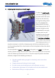
Tip: The lateral cheek piece contact should if possible be in a straight line with
the barrel axis.
• All functions accessible in the shooting position
• High positioning using knurled screw
• Bench rest cheek piece with special rear shape
• Easy setting of height, side and length
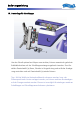
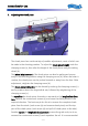
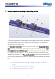
The grip is fastened to a ball-and-
socket joint allowing every possible
movement about this center-point.
In addition, the position of the grip
can be moved in the longitudinal
direction, sideways and in its
height. For longitudinal adjustment
and lateral displacement, undo
screw (a) and move the grip to the
required longitudinal and lateral
position. The lateral displacement is
achieved by turning the eccentric
disk from above. Then fix this
setting using the screw (a). The
height of the grip can be changed
when the clamping screw (b) is undone. Ensure here that the screw (c) is flush
with the flat surface of the grip.
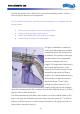
The three-dimensional inclination and rotation out of the middle plane of the
grip is set using the ball-and-socket joint fixed using the screw (c). To alter its
setting, undo the screw (c), set the required position of the grip and lock it in
this position using the screw (c).