
Product Manual
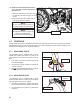
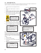
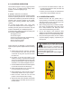
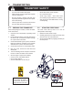
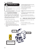
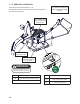
Table Of Contents
- DELIVERY INSPECTION REPORT
- label information
- SERIAL NUMBER LOCATION
- 1 INTRODUCTION
- 2 SAFETY
- 3 SAFETY SIGNS
- 4 OPERATION
- 5 TRANSPORTING
- 6 STORAGE
- 7 SERVICE AND MAINTENANCE
- 8 TROUBLE SHOOTING
- 9 SPECIFICATIONS

21
14. Ensure that the PTO driveline has been
cut to size (see section 4.5) Install the
PTO drive line:
a. Slide the collar back on the yoke, align
the splines and slide the yoke on the
tractor.
b. Release the collar and make sure the
locking pin clicks into position.
NOTE
Be sure the telescoping portion of
the shaft is greased and free of dirt.
PTO Driveline
4.7.1 DISCHARGE CHUTE:
The discharge chute is designed with a spring-
loaded latch handle that allows the chute to be
positioned 270° then locked into position with the
latch.
1. Push down on the latch handle until the chute
lock pin disengages.
2. Use the latch and grip handles to position the
chute as required.
3. Release the latch handle and lock the chute into
position at the next nearest lock point.
4.7.2 HOOD DEFLECTOR:
The discharge chute is equipped with a spring
tensioned hood deector on the end of the chute to
direct the chips exactly where desired.
1. Lift and push forward the adjustor grip handle
and move the deector into position as required.
2. Lock the deector into position by pulling back
and down.
Grip Handle
Latch Handle
Deector
Adjuster
Deector
4.7 CONTROLS
Please review this section to familiarize yourself with the location and function of each control before starting.
Familiarizing yourself with the controls will enable you to take advantage of all the features available on the
BX Chipper and apply them as conditions demand.
NOTE
Ski adjustment may be required for
best PTO operating angle.
(see Section 4.8 Machine Setup)