
Install Manual


14
EN
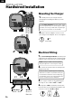
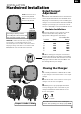
Electrical Wiring
L2L1
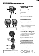
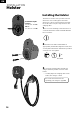
Mounting the Charger
Hot wires
Black + Red
Ground
Green or
Bare wire
INSTALLATION
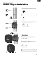
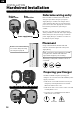
Hardwired Installation
x2
ø3.5 x 9.5mm
1. Carefully remove your charger from the
packaging box and hang it from the top of the
wallplate.
1. For bottom wiring installation, feed the power
supply wires through the bottom port with enough
length to easily connect the wires to the terminals.
2. Replace the two wallplate screws to secure
your charger to the wallplate. Do not over-tighten
2. Connect the electrical wires according to the
diagram on the left.
3. Use copper conductors only within the wire
size range of 10 to 6 AWG (6mm
2
to 16mm
2
)
4. Strip 1/2” (12mm) of insulation o each wire,
insert the wires per the diagram, and tighten each
connector screw to 11.5in·lbs (1.3N·m)
For rear wiring installation, feed the power supply
wires through the rear port (and through the rubber
grommet, if not using conduit) with enough length
to easily connect the wires to the terminals
NOTE: If using a conduit connection, pull the
wiring through before connecting the conduit
Ensure the electrical panel supports a 208/240V
dedicated circuit with a new, dedicated two-pole
circuit breaker, rated for the selected amperage
(see following section). The voltage between the
hot wires (L1 and L2) must be 208/240V.