PULSAR PLUS Installation Guide
EN INDEX GETTING STARTED Data Sheet Safety Instructions Package Contents Before Installing Prepare the Charger for Installation Location Positioning 3 4 7 8 8 8 8 INSTALLATION NEMA Plug-in Installation Existing NEMA Outlet NEMA Outlet Installation Placement Installing the Wallplate Mounting Hardwire Installation Determine Wiring Entry Placement Preparing you Charger Removing the NEMA 14-50P Cable Installing the Wallplate Mounting the Charger Electrical Wiring Rated Current Adjustment Closing the Charger
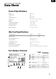
EN GETTING STARTED Data Sheet General Specifications Model Cable length Color Charging protocol Dimensions Weight Operating temperature Storage temperature Pulsar Plus 25ft Matte Black SAE J1772 7.8” x 7.9” x 3.9” (without cable) 4.4lbs (without cable) -22ºF to 104ºF -40ºF to 158ºF Electrical safety EMC compliance UL 2594, UL 2231 FCC Part 15 Class B Electrical Specifications Charging Power 9.6kW 11.
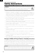
EN GETTING STARTED Safety Instructions SAVE THESE INSTRUCTIONS | INSTRUCTIONS PERTAINING TO RISK OF FIRE OR ELECTRIC SHOCK WARNING: When using electric products, basic precautions should always be followed, including those below. This manual contains important instructions that cover the safe installation, operation and maintenance of the unit. • Read all instructions before installing and using your Wallbox charger.
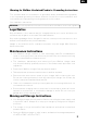
EN Warning for Wallbox Hardwired Products: Grounding Instructions This product must be connected to a grounded, metal, permanent wiring system, or an equipment-grounding conductor must be run with the circuit conductors and connected to the equipment grounding terminal on the product. See installation instructions.
EN FCC Note This equipment has been tested and found to comply with the limits for a Class B digital device, pursuant to part 15 of the FCC Rules. These limits are designed to provide reasonable protection against harmful interference in a residential installation. This equipment generates, uses and can radiate radio frequency energy and, if not installed and used in accordance with the instructions, may cause harmful interference to radio communications.
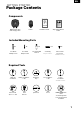
EN GETTING STARTED Package Contents Components PULSAR PLUS Amperage Reduction Label Wallbox Chargers S.L. SN: 123456 UID: abcdefgh PN: PUP1-U-1-5-N-002-A 22ºF to 104ºF (-30ºC to 40ºC) Enclosure Type 3R Input/Output: 208/240VAC, 60Hz, 48A EV Charger 20A 08/2020 Made in Spain Product label Circuit Breaker Place the appropriate Input/Output label on top of the charger’s label. Label the breaker with the selected amperage value.
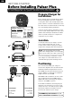
EN GETTING STARTED Before Installing Pulsar Plus Before installing your charger, be sure to obtain any required permits and/or approvals in accordance with applicable codes, regulations, and ordinances for electrical installations. Prepare Charger for Installation Before getting started, carefully lift the charger from the packaging, remove the cardboard covering the cables, and carefully unfasten the plastic cable ties on the EV cable bundle.
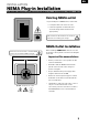
EN INSTALLATION NEMA Plug-in Installation Refer to one of the corresponding sub-sections below for an existing NEMA outlet or for installing a new NEMA outlet. Existing NEMA outlet If you already have a NEMA outlet, ensure that: • It complies with local electrical codes. • It has a designated circuit breaker and electrical wiring that are dimensioned appropriately. Switch off the circuit breaker of the electrical outlet before installing your charger.
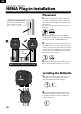
EN INSTALLATION NEMA Plug-in Installation Ensure the NEMA receptacle is correctly installed before connecting your charger. See instructions on Page 9. Follow our recommendations for location and positioning the charger in page 8 Placement 1. Using a wall stud finder, find the wall stud nearest to the NEMA outlet. Mark a vertical line approximately 20” (50cm) in length in line with the wall stud. Alternately you may find a suitable location on a solid wall. 2.
EN INSTALLATION NEMA Plug-in Installation 3. Drill two holes with an appropriate sized bit. Place the wallplate in alignment with the holes If you are mounting your charger on a solid wall, use the wall anchors provided with your charger x2 4. Firmly mount the wallplate using the provided wall screws. Do not over-tighten the screws. x2 ø6 x 45mm Mounting 1. Carefully remove your charger from the packaging box and hang your charger from the top of the wallplate. 2.
EN INSTALLATION Hardwired Installation Installation of your Wallbox charger with a permanent power supply Bottom Connection Rear Connection Power supply/wiring Determine wiring entry Before hardwire installation, determine which entry port you will be using for your power supply wiring or conduit. Your charger can be connected from either the rear or bottom entry ports. Choose the most appropriate connection based on the placement of your wiring or conduit.
EN INSTALLATION Hardwired Installation Removing the NEMA 14-50P cable 40A NEMA Model only 1. To disconnect the NEMA power cable wiring, unscrew the terminal screws as shown in the diagram on the left. 2. Loosen the left cable gland in a counter- clockwise direction and pull down on the NEMA cable to release it from your charger. Safely store or dispose of the NEMA cable.
EN INSTALLATION Hardwired Installation Mounting the Charger 1. Carefully remove your charger from the packaging box and hang it from the top of the wallplate. For rear wiring installation, feed the power supply wires through the rear port (and through the rubber grommet, if not using conduit) with enough length to easily connect the wires to the terminals 2. Replace the two wallplate screws to secure your charger to the wallplate. Do not over-tighten x2 ø3.5 x 9.5mm Electrical Wiring 1.
EN INSTALLATION Hardwired Installation 40A-versions are set to Position 6 by default 48A-versions are set to Position 7 by default Current selector 9 0 6 2 3 7 8 1 Selecting a switch position exceeding the rated current will not exceed the rated current. 4 5 CAUTION To reduce the risk of fire, only connect your charger to a circuit with a branch circuit overcurrent protection of 125% of the selected max amperage setting of the device in accordance with ANSI/NFPA 70 (US) C22.
EN INSTALLATION Holster Installing the Holster Installation Height Outdoor: 18 - 48” (45 - 120cm) Indoor 24 - 48” (60 - 120cm) The holster is used to store your EV connector when not in use. You may place the holster wherever it is most convenient, being sure that the location does not place any tension on the charging cable. 1. For a secure mounting, locate the holster on a vertical wall stud or similar solid wall. Mark the two screw holes. 2.
EN Operating NOTE: Once you have powered on the connected circuit, your charger will be ready to charge your EV. To fully access your charger functions and control your charger remotely, however, you will need to download the myWallbox app to a mobile device (smartphone or tablet) and register your charger following the directions below Powering on If you have installed a NEMA plug-in model, insert the NEMA plug in the receptacle.
EN Operating Compatibility This Wallbox charger can be used with any Battery or Plug-In Hybrid Electric Vehicle (BEV/PHEV) that is compliant with SAE J1772 (Including Teslas using the Tesla provided adapter) Charging AMPS 40 CONNECTED With your charger powered, connect the EV connector to your vehicle’s charge port/input. Connecting your charger will automatically initiate the charging process.
EN Service Need more assistance? Contact Wallbox customer service: (888) 787-5780 support.wallbox.com service.na@wallbox.com www.wallbox.com service.na@wallbox.
support.wallbox.com V-1.