
User Manual

Guilin Feiyu Electronic Technology Co., Ltd
Guilin Feiyu Electronic Technology Co., Ltd http://www.feiyudz.cn E-mail: service@feiyu-tech.com Page 3
l Pin interface to sort the list
8
7
6
5
4
3
2
1
NO.
GND Power P1 P2 GND 3.3V
TX0
RX0
Ⅰ
RUD THR ELE AIL GND Power
TX1
RX1
Ⅱ
Power Power Power Power Switch 1
Rudder
Throttle
Elevator
Ⅲ
GND GND GND GND GND Power
Aileron
Switch 2
Ⅳ
NOTE: The pin”I-1,2,3,4”is for the GPS module, “I-3”pin output
+3.3V, so please don’t supply to this pin, or will burn the
FY-31AP.
l DIP Switch Function:
Switch
number
1 2 3 4
ON
For Factory
use only
Flight Mode
Selection
Flight Mode
Selection
Adjust
fligh
t
patterns
OFF
Always OFF
position
Flight Mode
Selection
Flight Mode
Selection
Normal
mode
Note:
l In this manual, the direction for all the DIP switches is shown by
white color .
l the position for the DIP switch 1 is OFF, if it was put in ON, then the
FY-31AP cannot work normally.
l GPS features
The FY31AP GPS pin interface consist of: GND, 3.3V voltage, TX0, RX0.
The characteristics are:
· Data bits: 38400
· Interface Features: TTL level
· Data bits: 8
· Stop Bits: 1
· Parity: None
Connect the above to the GPS Receiver. The GPS data protocol is a
standard NEMA0183 and the statement must be $ GPRMC, $ GPGGA.
NOTE: The pin”I-1,2,3,4”is for the GPS module, “I-3”pin output
+3.3V, so please don’t supply to this pin, or will burn the
FY-31AP.
l UART Interface
The UART pin interfaces consist of: GND, power, TX1, RX1. The
characteristics are as follow:
· Baud Rate: 19200
· Data bits: 8
· Stop Bits: 1
· Parity: None
· Interface features: TTL
The pin interfaces output telemetry data. This interface connects to the
data radio, PC computer serial port or OSD module. You can set the
flight route, navigation and control parameters of FY31AP by this
interface. The port is also used to upgrade FY31AP firmware.
Please read the procedure for the firmware upgrading.
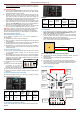
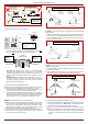
l FY-31AP Electrical Connection and Diagram
a) Power supply
l The FY-31AP operates between 4 to 6 volts input.
l FY-31AP is powered via the Receiver connection.
l If your plane is Electric powered, the Receiver power supply is
normally from the ESC built-in Battery Elimination Circuit (BEC).
However, we highly recommend that a separate BEC with a 3A
output.
l For Gas or Nitro powered planes, you will require a battery to power
the Receiver and FY-31AP.
b) Connections The FY31AP is
connected to your RC Receiver
via a 6 wire cable. You need a
minimum 6 Channel RC
Receiver.
l FY-31AP requires a minimum
of 6-channel RC receiver.
l 4 Receiver channels are used for aileron (channel 1), elevator
(channel 2) ,throttle (channel 3) and rudder (channel 4) signal
output. Connect these 4 receiver output signals to the FY-31AP with
the supplied wires (pay attention to the color of each channel ).
l 2 free Receiver channels are required to control the FY-31AP Flight
Modes (3-position switch or dial knob, ”SW1”) and Autopilot
Mode (3-position switch or dial knob, ”SW2”).
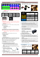
c) Note that the wire is arranged according to color :
Wire color
Receive channel
White
(bundled with red
& black)
aileron Channel 1
orange elevator Channel 2
green
throttle
Channel 3
yellow rudder Channel 4
brown
SW 1
Any free channel controlled by
3
-
way switch or dial knob
Channel 5
blue
SW 2
Any free channel controlled by
3
-
way switch or dial knob
Channel 6
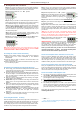
17. Vibration damping
A. FY-31AP is vibration-sensitive. To optimize its stabilization capability,
vibrations reaching the unit must be kept at a minimum.
B. When installing this flight stabilizer, we highly recommend that you
install it with the supplied vibration absorbing pads (dampers).
C. The algorithm in the FY-31AP compensates for normal levels of flight
vibration. However, if the vibration experienced by the unit exceeds
the acceptable level, it will not work normally or may even stop
working altogether.
D. To keep vibration at a minimum, install the FY-31AP away from the
engine or any other vibration sources.
E. The included shock-absorbing pads will
meet the damping requirements for
electric powered aircrafts and most gas
/ nitro planes.
F. The FY-31AP is supplied with the
double-sided foam padding dampers.
Please use them as shown:
l Checking for Vibration Levels
Even with the shock absorbing mount, your
aircraft installation may not meet the damping requirements of the FSS.
To confirm correct vibration damping, please follow this procedure:
A. After connecting all wires between the FY-31AP,Receiver and ESC,
install the unit as recommended (ensure correct orientation).
B. Run the plane engine or motor at different throttle levels. DO NOT
TAKE OFF.
C. Move the throttle level to different positions and maintain it for 20
seconds at each position.
D. At each throttle position, observe the state of the red LED light. If it
stays OFF, that means your vibration level is acceptable.
E. If instead the red LED lights up bright and stays ON solid, then the
vibration dampening is not enough. You will need reduce the level of
vibration on your aircraft, add additional dampening support or
change the installation location.
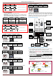
18. SW 1 and SW 2 : Switch Settings for FY31AP
a. SW-1 Flight Modes
The FY31AP has 3 Flight modes
controlled via SW-1. To select the modes,
use a free Receiver channel controlled via
a 3 way-switch:
FY-31AP flight modes
SW-1 signal output
900-1200us 1200-1800us 1800-2100us
Functional mode
Deactivated
Mode
Auto Stabilize
Mode
Path
Navigation
Mode
Blue LED light
indicator
continuous flash
Stay on solid Single flash
1
2
3