
User Manual

Guilin Feiyu Electronic Technology Co., Ltd
Guilin Feiyu Electronic Technology Co., Ltd http://www.feiyudz.cn E-mail: service@feiyu-tech.com Page 2
circle is the point of activation
. The default circle radius is 80 meters.
The aircraft altitude will be automatically maintained throughout the
ACM.
Autopilot stall warning
a. The FY-31AP has some control over the throttle channel. Therefore,
when flying in Autopilot Modes, please ensure you have enough
forward movement to prevent stalling.
b. FY-31AP may have a control over the throttle channel, but the
throttle control signal is base on the stick control signal and will
auto adjust according the altitude and speed then output the
combined signal. If your forward movement cannot compensate for
the autopilot’s active altitude hold, your aircraft will stall.
c. This is especially important if RTL is part of your RC failsafe. In the
event of RC Link lost, you can set RTL into your Receiver failsafe.
However, please DO NOT forget to also set your throttle failsafe to
between 25 % to 50% to ensure the plane does not stall.
d. Never set your throttle failsafe to zero. If you do so, your aircraft will
RTL in a continuous stalled flight which will result in a crash.
Attention: FY-31AP can work in automatic flight mode, though without
OSD module. Whether you have been connected the OSD or not,
FY-31AP can work normally. But if the FY-31AP is not connected GPS
module, it will function as purely as a flight stabilizer. The autonomous
flight modes cannot be engaged.
11. Red LED Flashing & Gyroscope Re-set:
If the following conditions occur, the FY-31AP initialization is
recommended:
(1) The device has not been used for a long time.
(2) There is a change in environmental temperature of over 30 degrees
since last flight.
(3) The Red LED flashes continuously even when the FY-31AP remains
stationary about 20s, and you never activate the motor.
(4) If the Red LED is on solid all the time even when the FY-31AP is
stationary, it means the gyroscope is faulty, and the unit need to be
sent back for repair.
12. Gyroscope Re-set procedures:
(1) Carry out this re-setting procedure only if the above occur. We do
not recommend regular re-setting. It is not necessary and not
recommended.
(2) The stabilizer unit does not need to be in a horizontal position
during initialization. However, you must ensure there is no vibration
during this process. If you suspect shaking occurred, just restart the
initialization / resetting process.
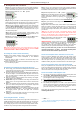
Initialization / Reset Process
(1) Install the jumper as shown in this
picture:
(2) Power-ON the FY-31AP and keep
it stationary for at least 20
seconds. You will notice the red
light blink with two different rates.
(3) After 20 seconds, the re-setting / initialization is complete.
(4) Disconnect the power, unplug the jumper & remove it (keep safe for
future use).
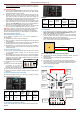
13. Flight mode Indicator (Red or Blue light)
By observing the flight indicator, you can easily re-confirm your Flight
Mode switch settings of your radio.
Blue light:
Flight
mode
Stabilized
Mode
Deactivated
Mode
Path
Navigation
Mode
Return To
Launch
(RTL)
Auto Circling
(ACM)
Blue LED
light
indicator
Stay on
solid
continuous
flash
Single flash
Double
flash each
loop
Continuous
flashing 3
times each
loop
14. GPS status & vibration level indicator
You can check the GPS lock status and vibration level by observing the
Red LED.
Red light:
Status
Too much
vibration
No GPS or
GPS still
not lock
Need to
initialize
Gyro or are
moving
GPS location
fixed
(4 satellites)
Red LED
light
indicator
Stay on
solid
Stay off solid
Continuous
flashing
Continuous
double flash
each loop
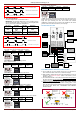
15. GPS Receiver
a. If GPS cannot fix the aircraft location (minimum 4 satellites), only
Mode 1 (Deactivated) and Mode 2 (Stabilized Mode) will function.
Mode 3 and Autopilot will not be functional.
b. Install the GPS Module with the antenna face up (see following
picture). DO NOT install next to metal or carbon fiber and other
shielding material, which may block satellite signal.
c. Install the GPS Module away from electromagnetic sources such as
ESC’s, power wires, servo wires and video transmitters.
GPS – Satellite Signal Lost During Autonomous Flight
l
GPS provides the aircraft geographic positioning, altitude, speed and
flight direction.
l Only if the GPS Data is available will the FY31AP perform its
Autopilot Modes.
l In case GPS signal is lost during flight , the autopilot will keep its
height and course (not lock)in automatic navigation mode ,but its
course may gradually drift. After GPS signal is regained the plane
will resume the Autopilot Mode.
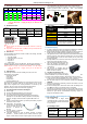
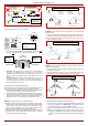
16. FY-31AP INTERFACE
POINT ARROW FORWARD
(TOWARDS FLIGHT DIRECTION)
2
3
4
5
6
7
8
1
Function DIP
J
umper installed
during gyro
initialization.
Do not insert
jumper during
normal use.
Red LED: the GPS
status & vibration
level indicator
Rudder
sensitivity
knob
Aileron
sensitivity
knob
Elevator
sensitivity
knob
Blue LED:
Flight mode
indicator.
Interface pin
panel
Ⅳ
Ⅲ
Ⅱ
Ⅰ
Green--Signal
Red
---
+3.3V
Black
-
-
GND
FY
-
31AP