OWNER’S MANUAL Safety, Assembly, Operating, and Maintenance Instructions and ILLUSTRATED PARTS MANUAL IH6620 Implement Hitch, RB6650 Rotary Broom, DB6660 Dozer Blade, SB6670 Two-Stage Snowblower and DB6680 Debris Blower Please Read and Save These Instructions For Safety, Read All Safety and Operation Instructions Prior to Operating Machine Effective Date 06-01-01 P/N I375 Price $5.
Foreword Thank you. . .for purchasing a Walker implement. Every effort has been made to provide you with the most reliable product on the market, and we are sure you will be among our many satisfied customers. If for any reason this product does not perform to your expectations, please contact us at (970) 221-5614. Every customer is important to us. Your satisfaction is our goal. Please. . .
Table of Contents Owner’s Manual General Information ________________ 1 HIGHLIGHTED INFORMATION _____________ GLOSSARY ____________________________ IDENTIFYING NUMBER LOCATIONS ________ SERVICING OF DRIVETRAIN GEARBOX ____ UNIT DESCRIPTIONS ____________________ Implement Hitch _______________________ Dozer Blade __________________________ Rotary Broom _________________________ Two-Stage Snowblower _________________ Debris Blower _________________________ 1 1 1 3 3 3 3 3 3 3 Specifications _____________
Table of Contents Maintenance Instructions __________ 43 Removal and Storage Instructions _ 68 MAINTENANCE SCHEDULE CHART _______ LUBRICATION _________________________ Rotary Broom Gearbox ________________ Rotary Broom Drive Chain _____________ Two-Stage Snowblower Gearbox ________ Two-Stage Snowblower Reduction Chain______________________ Grease Fitting and Oil Point Lubrication __ Implement HItch _____________________ Dozer Blade ________________________ Rotary Broom _______________________ Two-Stage S
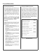
General Information HIGHLIGHTED INFORMATION IDENTIFYING NUMBER LOCATIONS Walker Manufacturing recommends that any service requiring special training or tools be performed by an authorized Walker Mower Dealer. There are several general practices to be aware of in the area of safety. Most accidents associated with the operation or maintenance of a Walker product are caused by disregarding basic safety precautions or specific warnings.
General Information Serial Number Serial Number Two-Stage Snowblower Serial Number Location (Rear View and RH View) Implement Hitch Serial Number Location (Top View) Serial Number Serial Number Dozer Blade Serial Number Location (Rear View) Serial Number Rotary Broom Serial Number Location (Rear View) 2 Debris Blower Serial Number Location (Rear View and RH View)
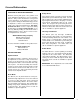
General Information SERVICING OF DRIVETRAIN GEARBOX Rotary Broom Detailed servicing and repair of the gearbox used on the implement attachments is not covered in this manual. Only routine maintenance and general service instructions are provided. For the service of the gearbox during the limited warranty period, it is important to find a local, authorized servicing agent of the component manufacturer. Any unauthorized work done on these components during the warranty period may void the warranty.
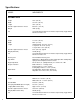
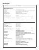
Specifications MODEL IMPLEMENTS IMPLEMENT HITCH Height 10 in. (25 cm) Width 33-1/2 in. (85 cm) Length 30 in. (76 cm) Overall Length Installed on Tractor 69-3/4 in. (177 cm) Weight 70 lb (32 kg) Lift 12 Volt DC Electric Ram Linear Actuator, Operated by Toggle Switch Mounted on FSC Lever DOZER BLADE Height 17-1/2 in. (44 cm) Width 46 in. (117 cm) Length Standard Hitch: 22-1/2 in. (57 cm) Long Hitch: 28-1/2 in. (72 cm) Longest Hitch: 35 in.
Specifications MODEL IMPLEMENTS ROTARY BROOM (continued) Hitch System Patented Quick Hitch System Type Brush 18 in. (46 cm) Diameter Polypropylene or Steel, Clockwise Rotation Brush Drive PTO Shaft Driving Center Mounted Gearbox Primary Reduction Gearbox, 2.78:1 Ratio Secondary Reduction #40 Chain and Sprockets, 3.27:1 Ratio Maximum Brush Speed 260 RPM Broom Angle Adjustment Five Positions, 0° (Straight Ahead), 12.5° and 25° LH or RH Working Width At Maximum Angle (25°) 39-3/16 in.
Specifications MODEL IMPLEMENTS DEBRIS BLOWER Height 28-1/2 in. (72 cm) Width 26 in. (66 cm) Length 34-3/4 in. (88 cm) Overall Length Installed on Tractor 102-1/2 in. (260 cm) Weight (With Female Hitch) 130 lb (59 kg) Lift 12 Volt DC Electric Ram Linear Actuator, Operated by Toggle Switch Mounted on FSC Lever Hitch System Patented Quick Hitch System Type Blower 13-1/2 in.
Component Identification NOTE: Control Identification shown in IMPLEMENT HITCH Operating Instructions section and in Illustrated Parts Manual.
Component Identification DOZER BLADE Welded Blade Angle Adjustment Pin Trip Spring Trip Spring Lockout Pin Skid Shoe Bracket Hitch Box Female Quick Hitch Trip Spring Lockout Bracket Skid Shoe Dozer Blade Rear View and Right Side View (Not Installed) 8 Skid Shoe Pin
Component Identification ROTARY BROOM Tension Spring Rotary Broom Housing Stopper Pin Ground Contact Knob Pivot Bracket Broom Angle Adjustment Lever Female Hitch PTO Shaft Plastic Wheel Brush Parking Stand Rotary Broom Rear View and Right Side View (Not Installed) 9
Component Identification TWO-STAGE SNOWBLOWER Deflector Deflector Position Control Knob Hand Guard Chute Chute Rotation Handle Gearbox Support Bracket Fan Auger Gearbox Frame Auger Two-Stage Snowblower Front View and Right Side View (Not Installed) 10
Component Identification Deflector Deflector Position Control Knob Chute Chute Rotation Handle Snowblower Housing Reduction Box Cover Skid Shoe Parallel Bar Skid Shoe Female Quick Hitch PTO Drive Shaft Two-Stage Snowblower Rear View (Not Installed) 11
Component Identification DEBRIS BLOWER Chute Rotation Handle Blower Motor Housing Belt Guard Linchpin PTO Drive Shaft Parking Stand Female Quick Hitch Pivot Wheel Debris Blower Front View and Left Side View (Not Installed) 12
Component Identification Chute Rotation Handle Belt Guard Parking Stand Pins Deflector Position Control Knob Driveline Guard PTO Drive Shaft Rotation Pinions Female Quick Hitch Parking Stand Debris Blower Rear View and Right Side View (Not Installed) 13
Safety Instructions Pay particular attention to any information labeled DANGER, WARNING, CAUTION, IMPORTANT, and NOTE in this manual. When you see the Safety Alert Symbol ( ), read, understand, and follow the instructions. Failure to comply with safety instructions may result in personal injury.
Safety Instructions 7. Do not wear loose fitting clothing that could get caught in moving parts. Always wear adequate protective clothing including long pants. Wearing safety glasses, safety shoes, and a helmet is advisable and required by some local ordinances and insurance regulations. OPERATING NOTE: Refer to the Walker Rider Lawnmowers OWNER’S MANUAL for safety instructions for operating the tractor. 1. Prolonged exposure to loud noise can cause impairment or loss of hearing.
Safety Instructions 12. Disengage the PTO clutch when transporting the machine. 13. Do not operate across the face of slopes. Use extreme caution when changing direction on slopes. Do not attempt to clear steep slopes. MAINTENANCE 14. Never adjust gauge wheels or skid shoes with the engine running. Before adjusting height or servicing, disengage the PTO clutch, stop the engine, and remove the ignition key. Wait for all movement to stop before getting off the seat. 1.
Safety Instructions SAFETY, CONTROL, AND INSTRUCTION DECALS Safety, Control, and Instruction Decals are installed on the machine. If any are missing, illegible, or damaged, a replacement should be ordered and installed before putting the machine into operation. The Decal Part Number is listed below and in the Parts Manual; the Decal Location is shown in the Parts Manual.
Safety Instructions SAFETY, CONTROL, AND INSTRUCTION DECALS Safety, Control, and Instruction Decals are installed on the machine. If any are missing, illegible, or damaged, a replacement should be ordered and installed before putting the machine into operation. The Decal Part Number is listed below and in the Parts Manual; the Decal Location is shown in the Parts Manual.
Assembly Instructions SETUP INSTRUCTIONS Walker Implements are shipped partially assembled. After uncrating the implement adaptor and/or implement(s), initial setup is required. NOTE: During the process of unpacking, any damaged or missing parts should be noted and reported to the delivering carrier immediately (put in writing within 15 days). The carrier will provide directions for proceeding with a claim to receive compensation for damage.
Assembly Instructions 4. Implement Hitch Wiring 1. Drill five (5) 13/64 in. (5 mm) diameter holes in the tractor, two in the FSC lever and three in the body, as shown in the illustration. Attach the toggle switch to the mounting bracket, placing the switch terminals toward the front of the mower. Mounting Bracket Wiring Clamps Switch Terminals Harness Drill Holes for Implement Hitch Wiring Attach Wiring Harness and Toggle Switch 2.
Assembly Instructions 6. Complete the wiring by connecting the wiring harness ends to the toggle switch and to the actuator motor of the implement hitch. Wire Harness Connector Actuator Motor Connector Complete Implement Hitch Wiring 7. Move the implement lift switch backward to raise the implement hitch to the UP position. 8. Move the implement lift switch forward to lower the implement hitch to the DOWN position. 9.
Assembly Instructions Implement Hitch Wiring Diagram 22
Assembly Instructions DOZER BLADE Nut Dozer Blade Assembly 1. Insert the female quick hitch into the hitch box on the blade attachment. 2. Align the single hole at the end of the female quick hitch with the single hole in the hitch box and insert the pivot pin through both holes. Secure the pivot pin on the underside with a 1/4 x 1 in. roll pin. Eyebolt Welded Tab Spring Hitch Box Attach Spring to Blade Assembly Pivot Pin 5. Insert a 3/16 x 1 in. split spring pin into the angle adjustment pin.
Assembly Instructions 8. Adjust the skid shoes to allow the required clearance under the blade. Install a skid shoe pin in each shoe and lock in place with a 4 mm x 80 mm hairpin. Refer to ADJUSTMENTS of Dozer Blade Skid Shoes in Maintenance Instructions. Linchpin Male Quick Hitch Female Hitch Skid Shoe Pin Hitch Locking Lever Skid Shoe Bracket Hairpin Attach Blade to Tractor 2. Skid Shoe Install Skid Shoes 9.
Assembly Instructions Male Quick Hitch Stand Support Bracket Female Hitch Hairpin Hitch Locking Lever Parking Stand Prepare Rotary Broom for Installation 3. Attach the female broom driveline half (with quick connect yoke) over the male broom driveline half. Set the driveline on its support. NOTE: Driveline sliding surfaces must be greased. Reduction Shaft Attach Broom to Implement Hitch 5.
Assembly Instructions 6. Remove the hairpin from the welded sleeve on the right hand side of the broom mounting bracket. Carefully pull out the stopper pin to its most extended position and lock in place with the hairpin. 8. Retract the parking stands and secure with the hairpins prior to operation. 9. To install the optional tire chains: a. Remove the tractor wheels. b. Attach the tire chains to the wheels. c. Place the wheel spacer plates on the lug bolts.
Assembly Instructions 1. Remove the pin and hairpin from each gauge wheel. Select the required number of spacer sleeves to remain on the bottom portion of the gauge wheels. Refer to ADJUSTMENTS of Rotary Broom Gauge Wheels in Maintenance Instructions. 2. Remove the parking stands and replace them with the gauge wheels. Place the remaining spacer sleeve(s) over the gauge wheels on the upper part of the stand supports, and secure the gauge wheels with the pins and hairpins.
Assembly Instructions 5. Insert the 1-11/16 in. (43 mm) plastic bushing into the bushing support and place this over the shaft on the rotation worm. 6. Install the rotation worm assembly through the tube weldment with the attaching plate of the support on the underside of the chute base lip. Tube Weldment 8. Bushing Insert two (2) 5/16 x 1 in. carriage bolts through each of the skid shoes from inside the bend.
Assembly Instructions Keyway 1/4 x 1/4 x 1-1/4 in. Key Reduction Box Cover Drive Shaft Yoke Bolt Set Screw Reduction Shaft Attach Drive Shaft Yoke to Reduction Shaft 4. Install Reduction Box Cover 6. Install one 1/4 x 7-1/2 in. bolt through the upper set of holes in the reduction box and secure loosely with a lock washer and nut. Attach the female portion of the hitch to the snowblower using one 3/8 x 1 in.
Assembly Instructions Clevis Female Hitch Male Quick Hitch Parallel Bar Clevis Hitch Locking Lever Attach Parallel Bar to Female Hitch Attach Snowblower to Implement Hitch 9. Attach the driveline quick lock coupler to the tractor PTO. WARNING 11. Insert the rotation handle into the rotation worm. Align the holes and lock in place with a 1/4 x 1 in. socket head cap screw and nylon locknut. 12. Install the plastic handle grip on the chute rotation handle. This shaft turns at high RPM.
Assembly Instructions 14. For GHS (Grass Handling System) equipped Walker tractors, install a blower intake cover in the blower intake tube. The cover “unloads” the blower and seals the intake to effectively eliminate power loss and noise when the blower is not being used. Refer to GHS Blower Intake Cover illustration for ROTARY BROOM in this section. 5. Reinstall the belt guard by reversing the removal procedure. 6.
Assembly Instructions 9. For stability of the tractor when transporting with the debris blower in raised position, approximately 80 lb (36 kg) of counterweight should be installed on the tail of the tractor. Optional tail weights for the various tractor models are available from your Walker dealer or a sandbag or similar weight may be used.
Assembly Instructions CHECK BROOM ANGLE ADJUSTMENT Refer to Angle Adjustment Lever in Operating Instructions. CHECK DRIVE CHAIN CHECK CHUTE AND DEFLECTOR • Make sure the chute and deflector are not clogged with snow and/or ice. • Turn the chute rotation handle and rotate the chute. The chute should rotate freely. Refer to LUBRICATION for Rotary Broom Drive Chain in Maintenance Instructions. Refer to ADJUSTMENTS of Rotary Broom Drive Chain Tension in Maintenance Instructions.
Operating Instructions Snow Removal WARNING Foreign objects in snow may be thrown farther than the snow. Use the slowest brush speed that will perform the job. Stay aware of the broom discharge direction at all times. 1. 2. The rotary broom works best on snow depths of 4 in. (10 cm) or less. Larger amounts of snow can be moved if the ground speed is reduced. To avoid snow being blown back onto the tractor and operator, sweep with the wind blowing in the direction of broom discharge.
Operating Instructions Engaging the Snowblower 1. Make sure that the snowblower is clear of snow and/or ice before engaging the snowblower. 2. Make sure that the auger and fan operate freely. 3. Check the oil level in the worm gearbox and if necessary, add SAE 90 E.P. (Extreme Pressure) oil. Make sure the oil level is up to the side plug. (Refer to LUBRICATION of Two-Stage Snowblower Gearbox in Maintenance Instructions.) 4.
Operating Instructions • When operating on a slope, reduce speed and use caution to start, stop, and maneuver. Avoid sharp turns or sudden changes in direction. • When blowing through deep snow drifts, let the snowblower work its way through the drifts. For best results, raise the snowblower and remove a top layer of snow, then pass through the area a second time to remove the remaining snow. • When snowblowing, operate the engine at or near full throttle for the best snowblowing action.
Operating Instructions DANGER DO NOT attempt to unclog the snowblower or make any adjustments with the tractor engine running. Disengage the PTO clutch, stop the engine, and remove the ignition key. Chute Rotation Handle DANGER NEVER place hands in the blower spout. DO NOT use hands or feet to unclog the snowblower. Use a short stick or similar tool to remove any clogged material. The following list of items should be checked if a pattern of clogging begins to develop.
Operating Instructions Engaging the Debris Blower 1. 2. Set the engine throttle at about 1/3 speed. DO NOT attempt to engage the PTO clutch at high engine speeds. This will drastically shorten drive belt life. Use only moderate engine speed when engaging the PTO clutch. Pull the PTO clutch lever SLOWLY to engage the debris blower. NOTE: For cold weather operation, allow sufficient time for the debris blower components to warm up before beginning to blow debris. WARNING the debris.
Maintenance Instructions CAUTION Maintenance procedures requiring special training or tools should be performed by a trained technician.
Maintenance Instructions LUBRICATION LUBRICATION 4. If the lubricant is flowing out of the plug hole, the gearbox is full. Reinsert the plug. If no lubricant flows out, add SAE E.P. (Extreme Pressure) 90W oil into the gearbox through the plug hole until it starts to flow out. 5. Wipe the threads of the gearbox plug before reinstalling. 6. Torque screws to 24 in-lb (2.7 N·m). WARNING DO NOT attempt to lubricate the machine with the tractor engine running.
Maintenance Instructions LUBRICATION Two-Stage Snowblower Gearbox Two-Stage Snowblower Reduction Chain The gearbox is permanently lubricated (oil filled) and sealed requiring no scheduled lubrication. However, the gearbox oil seal(s) should be checked every 25 hours for indication of an oil leak. If an oil leak is noted, replace the oil seal(s) and relubricate the gear-box as follows: Lubricate the reduction chain every 25 hours. A light penetrating oil or special purpose chain oil is recommended.
Maintenance Instructions Ident No. Location Lubrication Type LUBRICATION No. Places 5 6 Implement Hitch 1 2 3 4 46 PTO Shield Hinge Hitch Locking Lever Pivot Mounting Tube Sockets Hitch Lift Crank Ident No. Oil Oil Grease Grease 1 1 2 1 Location Hitch Pivot Shaft Quick Hitch Latch Lubrication Type Oil Oil No. Places 1 1 NOTE: Tractor Lubrication Points are not shown here. For Tractor Lubrication Points, refer to the appropriate Tractor OWNER’S MANUAL or ILLUSTRATED PARTS MANUAL.
Maintenance Instructions LUBRICATION Implement Hitch Lubrication Points 47
Maintenance Instructions Ident No. Location Lubrication Type LUBRICATION No. Places 5 6 Dozer Blade 1 2 3 4 48 Cutting Edge Skid Shoe Brackets (Grease Slide Area) Hitch Box Pin Trip Spring Lockout Bracket Pivot Pin Ident No. Oil Grease 1 2 Oil 1 Oil 1 Location Angle Adjustment Pin Female Quick Hitch Pivot Pin Lubrication Type Oil Oil No. Places 1 1 NOTE: Tractor Lubrication Points are not shown here.
Maintenance Instructions LUBRICATION Dozer Blade Lubrication Points 49
Maintenance Instructions Ident No. Location Lubrication Type LUBRICATION No. Places Rotary Broom 1 2 3 4 5 6 7 8 9 10 11 50 Chain Drive Sprocket Chain Drive Shaft Gearbox Wheel Brackets Angle Adjustment Lever Pivot Driveline Driveline Support Pivot Angle Adjustment Plate Universal Joint Shaft Assembly (Grease Slide Area) Ground Contact Knob Eyebolt Drive Chain Ident No. Location * Oil Grease Oil* Grease Oil Grease Oil Oil Grease** 1 1 1 2 1 1 1 1 1 Grease Oil 1 1 ** Lubrication Type No.
Maintenance Instructions LUBRICATION Rotary Broom Lubrication Points 51
Maintenance Instructions Ident No. Location Lubrication Type LUBRICATION No. Places Two-Stage Snowblower 1 2 3 4 5 6 7 8 9 10 11 52 Auger Sections Gearbox Cutting Edge Skid Shoes Gearbox Shaft Rotation Worm Reduction Chain Sprockets Parallel Bar Pivot Pins Universal Joint Shaft Assembly (Grease Slide Area) Rotation Handle Pivot Grease Oil* Oil Grease Oil Grease Oil Oil Oil Grease** 2 1 1 2 1 1 1 2 2 1 Oil 1 Ident No.
Maintenance Instructions LUBRICATION Two-Stage Snowblower Lubrication Points 53
Maintenance Instructions Ident No. Location Lubrication Type LUBRICATION No. Places Debris Blower 1 2 3 4 Front Gauge Wheel Plastic Anti-Friction Insert Air Blast Nozzle Sprockets Grease Grease Oil Oil 1 1 1 2 Ident No. 5 6 Location Lubrication Type Rotation Handle Grease* Universal Joint Shaft Assembly Grease* (Grease Slide Area) * No. Places 2 1 Grease every eight (8) hours. NOTE: Tractor Lubrication Points are not shown here.
Maintenance Instructions LUBRICATION Debris Blower Lubrication Points 55
Maintenance Instructions REPLACING/REPAIRING REPLACING/REPAIRING WARNING To prevent accidental engine starting when replacing parts or repairing the machine, remove the key from the ignition switch and disconnect the fuel solenoid wire [diesel engines] or the spark plug wire(s) [gasoline engines]. Reversible Cutting Edge CAUTION ALWAYS use genuine factory replacement parts. Substitute parts CAN result in product malfunction and possible injury to the operator and/or others.
Maintenance Instructions 6. Loosen the two sprocket set screws and push sprocket towards the brush. REPLACING/REPAIRING Rotary Broom Gearbox Remove and replace the gearbox as follows: Sprocket Chain Idler Chain Idler Bolt Sprocket Screws 1. Stop the tractor engine, set the parking brake, and remove the ignition key. 2. Loosen the set screw fastening the driveline female half and slide the driveline off the gearbox shaft. 3.
Maintenance Instructions 2. Loosen the bearing flange mounting nuts and bolts. Position the chain tension block so that the chain has as much slack as possible. Tighten the bearing flange mounting nuts and bolts slightly to hold the bearing flange in this position. REPLACING/REPAIRING 6. Adjust the chain. Refer to ADJUSTMENTS of Rotary Broom Drive Chain Tension in this section. 7. Reinstall the chain guard by reversing the removal procedures.
Maintenance Instructions 6. Align the slot in the new sprocket with the square key and slide the sprocket onto the drive shaft. Make sure the key is in place between the drive shaft and sprocket. Drive Sprocket REPLACING/REPAIRING 10. With the chain installed, recheck the sprocket alignment. 11. Lubricate the drive chain. Refer to LUBRICATION of Rotary Broom Drive Chain in this section.
Maintenance Instructions REPLACING/REPAIRING 4. Remove the two (2) 5/16-NC nylon locknuts and the two (2) 5/16-NC x 1-1/4 in. hex bolts fastening the support bracket and gearbox to the snowblower frame. 5. Hold and move the gearbox/auger assembly to the left and the right side will slide out. Slide the left side out. 6. Remove the two (2) 5/16-18 auger shear bolts and two (2) 5/16 nuts. Remove augers from gearbox/shaft assembly. 7. Replace the gearbox by reversing the removal procedures.
Maintenance Instructions REPLACING/REPAIRING 1. Remove the reduction box cover and reduction chain. Refer to REPLACING/REPAIRING of Two-Stage Snowblower Reduction Chain in this section. 2. Loosen the set screws that fasten the sprocket to the fan assembly by applying heat to the thread sealant used on these screws during assembly. 3. Slide the sprocket off the fan assembly. Use a puller if necessary. 4. Position the new sprocket on the fan assembly.
REPLACING/REPAIRING/ ADJUSTMENTS Maintenance Instructions 2. Loosen the three (3) nuts and three (3) bolts on lower pulley bearing support and the adjustment nut on the lower end of each (2) eyebolts to release belt tension. 3. Loosen the two (2) set screws securing the upper pulley bearing to the shaft. Unbolt and remove the upper pulley bearing support. Rotation Handle 4. Install the new drive belt and reinstall the upper pulley bearing support.
Maintenance Instructions ADJUSTMENTS 1/4 in. (6 mm) Clearance for Level, Paved Surfaces 1/2 to 3/4 in. (13 to 19 mm) Clearance for Uneven or Gravel Surfaces Pivot Bracket Upper Coupler Bolts Skid Shoe Height Adjustment Side to Side Level Adjustment Rotary Broom Brush Leveling IMPORTANT: The proper level adjustment of the broom is essential for efficient operation and life of the bristles. The broom should regularly be adjusted to prevent uneven brush wear. 1.
Maintenance Instructions ADJUSTMENTS Rotary Broom Drive Chain Tension Two-Stage Snowblower Skid Shoes The drive chain should have 1/4 to 1/2 in. (6 to 13 mm) of slack at midspan. Remove the chain guard cover to check slack. Adjust the drive chain as follows: Adjust the skid shoes to allow the required clearance under the blade. On level, paved surfaces, adjust the skid shoes to allow 3/16 to 1/4 in. (5 to 6 mm) clearance between the cutting edge and the surface.
Maintenance Instructions Decrease Chain Tension ADJUSTMENTS Linchpin Support Box Bolts Pivot Bushing Increase Chain Tension Gauge Wheel Reduction Chain Tension Adjustment Gauge Wheel Height Adjustment Debris Blower Front Gauge Wheel Debris Blower Drive Belt Tension Adjust the gauge wheel height according to surface condition. The drive belt deflection must be 1/8 in. (3 mm) when 6-1/2 to 9 lbf (29 to 40 N) is applied midway between the two pulleys.
Maintenance Instructions ADJUSTMENTS Rotation Handle Blower Pulley Bearing Support Bolts Upper Stop Ring & Set Screw Adjustment Eye Bolts Drive Belt Tension Adjustment Lower Support Debris Blower Rotation Pinions The two (2) rotation pinions should slightly contact each other without any resistance. 1. Loosen the set screw of each stop ring on the rotation handle. 2.
Maintenance Instructions TORQUE SPECIFICATIONS TORQUE SPECIFICATIONS 67
Removal and Storage Instructions REMOVAL Rotary Broom Removing Attachments from Implement Hitch 1. WARNING Dozer Blade 1. Park the tractor on a level surface and lower the dozer blade. DO NOT attempt to remove the rotary broom with the tractor engine running. Disengage the PTO clutch, stop the engine and remove the ignition key. Wait for all movement to stop before getting off the seat. WARNING DO NOT attempt to remove the dozer blade with the tractor engine running.
Removal and Storage Instructions PTO Shaft Welded Sleeve Hairpin Quick Hitch Lever PTO Shaft Pivot Lock Pin Hitch Locking Lever Detach Rotary Broom from Implement Hitch Detach Snowblower from Implement Hitch Two-Stage Snowblower 1. Park the tractor on a level surface and lower the snowblower. Debris Blower 1. WARNING DO NOT attempt to remove the snowblower with the tractor engine running. Disengage the PTO clutch, stop the engine and remove the ignition key.
Removal and Storage Instructions PTO Shaft Support Arms Hitch Locking Lever Quick Hitch Latch Parking Stand Detach Implement Hitch from Tractor Detach Debris Blower from Implement Hitch END OF SEASON STORAGE Removing Implement Hitch from Tractor IMPORTANT: Detach any attached implement from the hitch before detaching the hitch from the tractor. Refer to the instructions for REMOVAL of Dozer Blade, Rotary Broom, Two-Stage Snowblower, or Debris Blower in this section. 1.
Removal and Storage Instructions 3. 4. NOTE: Rustproofing or painting every year will prolong the life of the blade components and moving parts. Debris Blower 1. Clean the debris blower thoroughly. When the dozer blade is dry, lubricate all moving parts with SAE 30 engine oil. Apply oil liberally to all exposed surfaces to protect against rust. 2. Repaint all parts from which paint has worn.
IMPLEMENT HITCH ASSEMBLY ITEM NO. PART NO. DESCRIPTION NO.
IMPLEMENT HITCH ASSEMBLY Effective Date 06-01-01 Use only genuine Walker® replacement parts.
IMPLEMENT HITCH ELECTRICAL COMPONENTS ITEM NO. PART NO. DESCRIPTION NO. REQ’D Implement Hitch Electrical Components 1 2 3 4 5 6 6623-1 6628 6623 6632 5832 6622 6631 Switch Boot (Fits P/N 6623) Switch Mount Bracket Lift Control Switch Decal, Implement Hitch Cable Clamp (1/2) Wiring Harness, Actuator Implement Hitch Electrical Package ITEM NO. PART NO. DESCRIPTION NO.
IMPLEMENT HITCH ELECTRICAL COMPONENTS Effective Date 06-01-01 Use only genuine Walker® replacement parts.
DOZER BLADE ASSEMBLY ITEM NO. PART NO. DESCRIPTION NO.
DOZER BLADE ASSEMBLY Effective Date 06-01-01 Use only genuine Walker® replacement parts.
ROTARY BROOM ASSEMBLY ITEM NO. PART NO. DESCRIPTION NO.
ROTARY BROOM ASSEMBLY Effective Date 06-01-01 Use only genuine Walker® replacement parts.
ROTARY BROOM DRIVE COMPONENTS ITEM NO. PART NO. DESCRIPTION NO. REQ’D Gearbox Assembly 1 2 3 4 5 6 7 8 9 10 11 12 13 14 15 16 17 18 19 20 21 NS O/L NS NS NS NS NS NS NS NS NS O/L O/L NS NS NS NS NS NS O/L O/L Dipstick Plug (RAD 661741) M8 x 45 Bolt Casing (RAD 661740) Oil Seal (RAD 661730) Snap Ring (RAD 661734) 25.6 x 0.6 Shim (RAD 661733) Bearing (RAD 661732) 25.6 x 0.7 Shim (RAD 661731) Pinion, 29M3.
ROTARY BROOM DRIVE COMPONENTS Effective Date 06-01-01 Use only genuine Walker® replacement parts.
SNOWBLOWER HOUSING COMPONENTS ITEM NO. PART NO. DESCRIPTION NO.
SNOWBLOWER HOUSING COMPONENTS Effective Date 06-01-01 Use only genuine Walker® replacement parts.
SNOWBLOWER DRIVE COMPONENTS ITEM NO. PART NO. DESCRIPTION NO.
SNOWBLOWER DRIVE COMPONENTS Effective Date 06-01-01 Use only genuine Walker® replacement parts.
DEBRIS BLOWER COMPONENTS ITEM NO. PART NO. DESCRIPTION NO.
DEBRIS BLOWER COMPONENTS Effective Date 06-01-01 Use only genuine Walker® replacement parts.
DEBRIS BLOWER MANUAL ROTATION COMPONENTS ITEM NO. PART NO. DESCRIPTION NO.
DEBRIS BLOWER MANUAL ROTATION COMPONENTS Effective Date 06-01-01 Use only genuine Walker® replacement parts.
KEY TO ABBREVIATIONS USED IN ILLUSTRATED PARTS MANUAL Abbreviation What it Represents º (Dimension) .................................................................................................................... Degrees (Angle) " (Dimension) ....................................................................................................................................inches cfm ........................................................................................................................
LIMITED WARRANTY FOR WALKER COMMERCIAL RIDER MOWER 1. WHAT THIS WARRANTY COVERS, AND FOR HOW LONG: Walker Manufacturing company will, at its option, repair or replace, without charge, any part covered by this warranty which is found to be defective in material and/or workmanship within one (1) year* after date of sale to the original retail purchaser unless the product is used for rental purposes, in which case this warranty is limited to ninety (90) days.
WALKER MFG. CO. • 5925 E. HARMONY ROAD, FORT COLLINS, CO 80528 • (970) 221-5614 FORM NO. 060101 www.walkermowers.com PRINTED IN USA ©2001 WALKER MFG.