OPERATOR'S MANUAL AND SAFETY INSTRUCTIONS WITH INSPECTION AND MAINTENANCE INSTRUCTIONS TURBOMILL 40B MAGNETIC MACHINING CHUCK SERIES ELECTROPERM CHUCKS O.S. WALKER Rockdale Street, Worcester, MA 01606 (508)-853-3232 FAX (508)-852-8649 3508 Glenridge Drive, Chino Hills, CA 91709 (909)-597-4785 FAX (909)-597-0581 901 Arvin Avenue, Stoney Creek, Ontario, L8E5N9 Canada (905)-643-3338 In Canada: 1-800-267-4678 FAX (905)-643-6111 www.walkermagnet.com Email: info@walkermagnet.
TABLE OF CONTENTS 1 INTRODUCTION...............................................................................................................................................................1-1 2 SAFETY INSTRUCTIONS ................................................................................................................................................2-1 2.1 GENERAL SAFETY RULES ..........................................................................................................................
TABLE OF FIGURES FIGURE 4-1 BASIC MAGNETICS ...............................................................................................................................................4-3 FIGURE 4-2 MAGNETIC ATTRACTION .......................................................................................................................................4-4 FIGURE 4-3 CONVENTIONAL MILLING .......................................................................................................................
1 INTRODUCTION Thank you for purchasing this O. S. Walker, Inc. Chuck. If used and maintained properly, it should serve you for many years. However, if installed and used improperly it can be rendered inefficient and unsafe. Therefore, it is absolutely essential that anyone who uses this chuck and is responsible for its application be trained on how to use it correctly. Read this manual carefully to learn how to operate and maintain your chuck.
2 SAFETY INSTRUCTIONS 2.1 General Safety Rules Danger always exists when using industrial holding equipment, especially if the equipment is not being used properly or is poorly maintained. Because accidents and sever bodily injury or death can result, special safety precautions apply to the installation, operation, inspection, and maintenance of all holding equipment.
2.2 Recognize Safety Information This is the safety alert symbol. When you see this symbol on your chuck or in this manual, be alert to the potential for personal injury. Follow recommended precautions and safe operating practices at all times. This indicates a situation in which a hazard is imminent and will result in a high probability of serious injury or death.
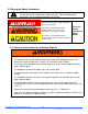
2.2.2 Additional Warnings • • • • Never operate damaged or malfunctioning chuck. Never remove or damage Operating and Warning labels. Persons using pacemakers or any other medical devices should not use this magnet until they have consulted with their physician. The electrically conductive body of this chuck must be connected to a proper electrical ground. • • • Disassembly or repair of this chuck control can result in reduced holding power and/or cause an unsafe condition.
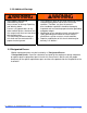
2.4 Electrical Ground ELECTRICAL GROUNDING Because the O. S. Walker Co. does not know the specifics of each application and installation of these products and the electromagnetic device to which they are attached, it can only warn the installer and user that the electrically conductive body of the electromagnetic device MUST be connected to a proper electrical ground. According to ANSI/NFPA 79 1997(an American National Standard) "Electrical Standard for Industrial Machinery": • Section 19.
3 INSTALLATION INSTRUCTIONS FOR MOUNTING THE CHUCK 3.1 Grinding the Mounting Surfaces of Rectangular Chucks A) Clean and degrease magnetic chuck. Soak chuck with WD-40 and let sit for 15 minutes to remove kosmolene. (Protective Coating) B) Check bottom surface for sharp edges or burrs. Use file or oil stone to remove them. C) Clean the machine's table surface and place the chuck, face down, on the sliding table of a surface grinder and indicate the surface of the chuck lengthwise and crosswise.
3.1.1 Connecting the Chuck The DC output to the chuck must include a ground wire that is connected to the safety ground lug on the chuck and to the chassis of the chuck control. It is recommended that the conduit for the DC output not be routed near high voltage AC wires. Many chucks are installed on machines with moving tables. Choose a means of wiring the chuck that allows adequate freedom of movement over the full range of table travel. O.S. WALKER Co. Inc., Turbomill Electroperm Chucks 3-2 DD15508M.
4 OPERATING INSTRUCTIONS 4.1 System Operation The electro-perm chucks operate via a chuck control. The control for this particular Electroperm chuck should be either a Walker VFR-10 or a Walker Smart 100T control. You can refer to the chuck control manual for detailed information on the installation and operation of this control. Use of other model controls could result in reduced holding force or cause permanent damage to the chuck.
4.3.2 Workpiece Surface Condition The holding capacity of the chuck will be reduced if certain surface conditions exist. A rough surface finish on the work piece creates an air gap. Foreign materials such as dirt, paint, rust, paper, and rags will create an air gap. 4.3.3 Workpiece Thickness The greater the number of lines of magnetic force flowing from a magnet into the work piece the greater the effectiveness of the magnetic chuck.
4.4 Guidelines for the Reduction of Rated Holding Capacity Each Walker chuck model is rated for different holding limits. Load characteristics will affect the holding capacity of the chuck. The holding guidelines for the chuck models are shown below. THIS TABLE PROVIDES SOME REDUCTION FACTORS FOR MATERIAL OTHER THAN SAE 1020 STEEL. Table 4-1 Reduction Factor for material other than SAE 1020 Steel Reduction factors for material other than SAE 1020 Steel Materials Reduction Factor Cast Steel 0.
Figure 4-2 Magnetic Attraction 4.5.1 Principles of Magnetic Work Holding The ability to hold a work piece magnetically on a milling chuck is dependent on the characteristics of the work piece itself and, of course, the degree of machine force exerted upon it. To establish the feasibility of a specific application, three key parameters must be considered. 1) Work Piece Material As a rule, though there are some exceptions, magnetic conductivity in a material decreases with greater alloy content.
4.6 Forces Generated by Milling Turbo-mill milling chucks can generate up to 5 tons/ft² holding force, so it is very unlikely that a work piece will lift away from the holding surface of the chuck. However, the resistance force to horizontal sideways movement is approximately four to five times less than the downward holding force. Consequently, if the cutting forces exceed the chuck’s resistance force to horizontal sideways movement, the work piece will slide in the direction of the forces.
4.6.2 Climb Milling The machining force F is downward toward the chuck and to the bottom right hand corner of the work piece. Therefore, the end stop is placed at the end where the cut starts. As the cut proceeds, the machining force helps to hold the work piece down onto the chuck face. This means that heavier cuts can be taken in climb milling. Figure 4-4 Climb Milling O.S. WALKER Co. Inc., Turbomill Electroperm Chucks 4-6 DD15508M.doc Rev.
4.6.3 Face Milling For on-center face milling, the action of the cutter tends to push the work up to the left hand end and to the side of the chuck because the center of the cutter is over the center of the work pieces. This condition cannot always be met, however, and it is sometimes necessary to position the work piece off-center in relation to the cutter. For off-center milling, the work piece is still pushed to the same side but towards the end stop on the right. Figure 4-5 Face Milling O.S.
4.6.4 Edge Milling In all cases, when the chuck is working to full capacity, it is better to climb mill the work piece into the side and end stops. However, the centerline of the cutter in relation to the edge of the work piece will have an adverse affect to the ultimate direction of the force exerted to the work piece. Note that the workpiece entry force and exit force directions are different. Therefore, for vertical edge milling, the cutting depth recommended limit is half the diameter of the cutter.
4.7 Workpiece Blocking Using Walker's heavy duty milling chuck, the smallest work piece to be held on the magnet should be at least 4" x 7-1/2". Smaller pieces will need blocking. Figure 4-7 Blocking O.S. WALKER Co. Inc., Turbomill Electroperm Chucks 4-9 DD15508M.doc Rev.
Figure 4-8 Blocking O.S. WALKER Co. Inc., Turbomill Electroperm Chucks 4-10 DD15508M.doc Rev.
Figure 4-9 Blocking Another option for smaller pieces would be to put them in a vise and put the vise on the magnet to machine the part. Call O.S. Walker and fax part size for help with difficult to hold work pieces. We will assist with proper blocking details. O.S. WALKER Co. Inc., Turbomill Electroperm Chucks 4-11 DD15508M.doc Rev.
4.8 Mild Steel Pole Riser Pole extensions are probably the most important and versatile pieces of tooling that can be used on O.S.W. milling chuck. We recommended that several sets of different heights be produced for your chuck as accessory tooling. Pole risers are useful for several reasons: 1) Locating surfaces for repeat operations. 2) Raise work for boring through operations. 3) Raise work up for access to sides. Figure 4-10 Fixed Riser Figure 4-11 Fixed Riser Figure 4-12 Adjustable Riser O.S.
Figure 4-13 Sliding & Fixed Pole Risers 4.8.1 How to Use Riser Blocks Each setup situation is unique and cannot be covered in this manual. The following are general guidelines for the use of riser blocks, fixed and adjustable. The workpiece should be supported at three points with fixed riser blocks, either individual or groups. The entire surface under the workpiece should be supported with adjustable riser blocks.
5 INSPECTION AND MAINTENANCE INSTRUCTIONS 5.1 Daily Inspection • Inspect the holding surface of your magnetic chuck. It must be clean, smooth, flat, and free of nicks or burrs in order to minimize the air gap between the chuck holding surface and the Work piece. All Walker chucks are designed with soft, low carbon steel magnetic poles in the chuck in order to maximize the holding capacity; therefore, special care must be taken to protect these areas. Regrind when necessary (see section 3.
6 RETURN AND REPAIR INSTRUCTIONS For warranty and non-warranty repairs on any part of your chuck system, contact O.S. Walker, Inc. TOLL FREE at 1-800-W-MAGNET. A return authorization number will be issued along with any applicable packaging and shipping instructions. After receipt of the components to be repaired, O.S. Walker, Inc. will perform an inspection and provide an estimate of the repair costs at no charge to the customer. Authorization from the customer must be obtained by O.S. Walker, Inc.