
Owner's manual

21
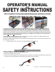
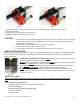
O.S. Walker Inc., NEO Permanent Lifting Magnets
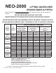
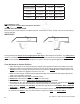
NEO-2000 LIFTING GUIDELINES
(ROUND BARS & PIPES)
Values shown are for maximum rated capacities when operating instructions and warnings are
followed.
VALUES ARE BASED UPON AISI 1020 STEEL
Higher alloy steels and other magnetic materials will require further reductions of these rated
capacities (See page 11 for the Guidelines for the reduction of the Rated Lifting Capacities.)
NEVER EXCEED EITHER THE MAXIMUM LENGTH OR WEIGHT SHOWN FOR EACH
ROUND BAR/PIPE DIAMETER, WALL THICKNESS & TYPE OF SURFACE CONDITION
Round
Bar/Pipe
Diameter
Inches
Pipe
Wall
Thickness
Inches
TYPE OF SURFACE CONDITION
CLEAN & SMOOTH
Similar to a Flat
(32 micro-inch RMS)
Ground Surface
.000” Max. Air Gap †
RUST OR SCALE
Similar to a Flat Hot Rolled
Steel Surface
.010” Max. Air Gap †
(.254mm)
IRREGULAR OR ROUGH
Similar to a Flat Smooth
Cut File
.020” Max. Air Gap †
(.508mm)
Maximum Length
Inches
Maximum Load
Pounds
Maximum Length
Inches
Maximum Load
Pounds
Maximum Length
Inches
Maximum Load
Pounds
13.75”
(350mm)
MAX DIAM.
3/4” 51” 440 48” 412 44” 385
1” 63” 715 53” 605 46” 522
SOLID BAR 52” 2200 47” 1980 42” 1760
11”
(279 mm)
3/4” 64” 440 60” 412 56” 385
1” 80” 715 68” 605 59” 522
SOLID BAR 82” 2200 74” 1980 65” 1760
8.625”
(220mm)
3/4” 84” 440 78” 412 73” 385
1” 105” 715 89” 605 77” 522
SOLID BAR 133” 2200 120” 1980 106” 1760
8”
(203mm)
3/4” 91” 440 85” 412 80” 385
1” 115” 715 97” 605 84” 522
SOLID BAR 155” 2200 139” 1980 124” 1760
6”
(152mm)
MIN DIAM.
3/4” 126” 440 118” 412 110” 385
1” 160” 715 136” 605 117” 522
SOLID BAR 196” 1570 177” 1415 157” 1255
NEVER LIFT ROUND BARS OR PIPES WITH:
A diameter LESS THAN 6 Inches or
A diameter GREATER THAN 13.75 Inches or
A wall thickness LESS THAN 3/4” (20 mm) or
A length greater than shown in the Lifting Guidelines above
(Absolute maximum length 196” (5000mm)
† Air Gap = nonmagnetic separation between magnet’s lifting surface and load.