
Owner's manual

15
O.S. Walker Inc., NEO Permanent Lifting Magnets
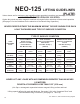
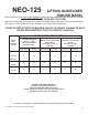
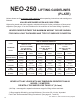
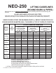
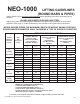
NEO-250 LIFTING GUIDELINES
(ROUND BARS & PIPES)
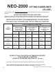
Values shown are for maximum rated capacities when operating instructions and warnings are
followed.
VALUES ARE BASED UPON AISI 1020 STEEL
Higher alloy steels and other magnetic materials will require further reductions of these rated
capacities (See page 11 for the Guidelines for the reduction of the Rated Lifting Capacities.)
NEVER EXCEED EITHER THE MAXIMUM LENGTH or WEIGHT SHOWN FOR EACH
ROUND BAR/PIPE DIAMETER, WALL THICKNESS & TYPE OF SURFACE CONDITION
Round
Bar/Pipe
Diameter
Inches
Pipe
Wall
Thickness
Inches
TYPE OF SURFACE CONDITION
CLEAN & SMOOTH
Similar to a Flat
(32 micro-inch RMS)
Ground Surface
.000” Max. Air Gap †
RUST OR SCALE
Similar to a Flat Hot Rolled
Steel Surface
.010” Max. Air Gap †
(.254mm)
IRREGULAR OR ROUGH
Similar to a Flat Smooth
Cut File
.020” Max. Air Gap †
(.508mm)
Maximum Length
Inches
Maximum Load
Pounds
Maximum Length
Inches
Maximum Load
Pounds
Maximum Length
Inches
Maximum Load
Pounds
7”
(178mm)
MAX. DIAM.
1/4” 30” 45 21” 32 18” 27
1/2 47” 137 35” 102 28” 82
1” 42” 225 28” 152 19” 102
SOLID BAR 25” 275 16” 180 10” 115
6”
(152mm)
1/4” 35” 45 25” 32 21” 27
1/2” 56” 137 41” 102 33” 82
SOLID BAR 34” 275 22” 180 14” 115
5”
(127mm)
1/4” 42” 45 30” 32 25” 27
1/2” 68” 137 50” 102 41” 82
SOLID BAR 49” 275 32” 180 20” 115
4”
(101mm)
1/4” 53” 45 38” 32 32” 27
1/2” 88” 137 65” 102 52” 82
SOLID BAR 77” 275 50” 180 32” 115
2 3/8”
(60mm)
MIN. DIAM.
1/4” 95” 45 67” 32 57” 27
1/2” 137” 137 122” 102 98” 82
SOLID BAR 137” 170 137” 170 91” 115
NEVER LIFT ROUND BARS OR PIPES WITH:
A diameter LESS THAN 2.375 Inches or
A diameter GREATER THAN 7 Inches or
A wall thickness LESS THAN 1/4” (6.4mm) or
A length greater than shown in the Lifting Guidelines above
(Absolute maximum length 137” (3500mm))
† Air Gap = nonmagnetic separation between magnet’s lifting surface and load.