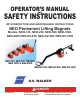
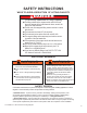
OPERATOR’S MANUAL SAFETY INSTRUCTIONS AND WITH INSPECTION AND MAINTENANCE INSTRUCTIONS NEO Permanent Lifting Magnets Models: NEO-125, NEO-250, NEO-500, NEO-1000, NEO-2000 NEO-HV-250, NEO-HV-500, NEO-HV-1000 NEO-125, NEO-250, NEO500, NEO-1000 & NEO-2000 NEO-HV-250, NEO-HV-500, NEO-HV-1000 WALKER • Always stay clear of the load. O.S. WALKER DANGER • Never lift loads over people or in close proximity to people.
CONTENTS INTRODUCTION ................................................................................................................................... 2 SAFETY INSTRUCTIONS .................................................................................................................... 3 GENERAL SAFETY RULES......................................................................................................................................3 RECOGNIZE SAFETY INFORMATION ................................
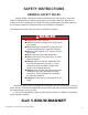
SAFETY INSTRUCTIONS GENERAL SAFETY RULES Danger always exists when loads are transported by lifting devices, especially when the equipment is not being used properly or is poorly maintained. Because accidents and severe bodily injury or death can result, special safety precautions apply to the operation, inspection, and maintenance of the Walker Lift Magnets. Following these simple rules can help to avoid lifting accidents: DANGER Always stay clear of the load.
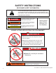
SAFETY INSTRUCTIONS RECOGNIZE SAFETY INFORMATION This is the safety alert symbol. When you see this symbol on your magnet or in this manual, be alert to the potential for personal injury. Follow recommended precautions and safe operating practices at all times. DANGER This indicates a situation in which a hazard is imminent and will result in a high probability of serious injury or death.
SAFETY INSTRUCTIONS WAYS TO AVOID A REDUCTION OF LIFTING CAPACITY DANGER To Avoid any Reduction of Lifting Capacity: The lifting surfaces of the magnet and the area of the load where the magnet will be located must be clean, smooth, flat and free of nicks and burrs. The full area of the magnet’s lifting surface must be in contact with the load. The load must be at least 2.5" (64 mm) thick. The load must be low carbon steel such as AISI 1020.
IMPORTANT FACTS FOR THE OPERATION OF LIFT MAGNETS LOAD CHARACTERISTICS OTHER THAN JUST WEIGHT MUST BE CONSIDERED IN ORDER TO DETERMINE THE LOAD THAT ANY MAGNET CAN LIFT. This statement is true for all lifting magnets because they all operate using the same fundamental laws of physics. Magnetic power is often pictured as lines of magnetic force flowing from north pole to south pole. Anything that limits the flow of these magnetic lines of force obviously reduces the magnet’s lifting capacity.
3. LOAD ALLOY Low carbon steels, such as AISI 1020 steel, are nearly as good conductors of magnetic lines of force as pure iron. However, many other alloys contain non-magnetic materials, which reduce the ability of magnetic lines of force to flow into the load. An alloy such as AISI 300 series of stainless steel is almost as poor a conductor of magnetic lines of force as air.
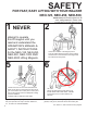
SAFETY FOR FAST, EASY LIFTING WITH YOUR WALKER NEO-125, NEO-250, NEO-500, 1 NEVER attempt to operate this lift magnet until you read and understand the OPERATOR’S MANUAL & SAFETY INSTRUCTIONS for the NEO-125, NEO-250, NEO-500, NEO-1000 AND NEO-2000 Lifting Magnets. 5 Check to be sure no one is near the load to be lifted. Inform others in the area that a lift is to begin. Lift the load 2 to 3 inches (50 to 75 mm) and then jar the load to insure that adequate holding power is available.
RULES LIFT MAGNETS MODELS: NEO-1000 & NEO-2000 unless the magnet is in contact with a load of a thickness equal to those listed manual. Attempting to energize or de-energize this magnet without a load or high probability of personal injury due to handle spring back. 3 4 Position the magnet so the load remains level. To energize magnet, grip the handle firmly and pull the handle from its locked position. Turn the handle to the “ON” position.
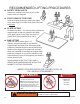
RECOMMENDED LIFTING PROCEDURES SAFETY HOOK LATCH Always use a safety hook latch on your crane hook to hold your magnets. STAY CLEAR OF THE LOAD Guide the load by pushing or pulling the edges of the load. Keep your entire body clear of the load at all times. PLATE LIFTING On plates less than 1 1/2” (38mm) thick, position the magnet length so that it is parallel to the width of the plate. Never lift any plate less than 1/4” (6mm) thick. (See Important Facts 2 & 4).
GUIDELINES FOR THE REDUCTION OF THE RATED LIFTING CAPACITY : Each Walker magnet model is rated for a different weight limit, and the load characteristics will affect the lifting capacity of the magnets. The lifting guidelines for the various models are shown on the following pages. The Lifting Guidelines charts show the effect of air gap, load thickness, load length, and load width on lifting capacity. As the thickness of the load decreases, so does the rated lifting capacity of the magnet.
NEO-125 LIFTING GUIDELINES (PLATE) Values shown are for maximum rated capacities when operating instructions and warnings are followed. VALUES ARE BASED UPON AISI 1020 STEEL Higher alloy steels and other magnetic materials will require further reductions of these rated capacities (See page 11 for the Guidelines for the reduction of the Rated Lifting Capacities.
NEO-125 LIFTING GUIDELINES (ROUND BARS) Values shown are for maximum rated capacities when operating instructions and warnings are followed. VALUES ARE BASED UPON AISI 1020 STEEL Higher alloy steels and other magnetic materials will require further reductions of these rated capacities (See page 11 for the Guidelines for the reduction of the Rated Lifting Capacities.
NEO-250 LIFTING GUIDELINES (PLATE) Values shown are for maximum rated capacities when operating instructions and warnings are followed. VALUES ARE BASED UPON AISI 1020 STEEL Higher alloy steels and other magnetic materials will require further reductions of these rated capacities (See page 11 for the Guidelines for the reduction of the Rated Lifting Capacities.
NEO-250 LIFTING GUIDELINES (ROUND BARS & PIPES) Values shown are for maximum rated capacities when operating instructions and warnings are followed. VALUES ARE BASED UPON AISI 1020 STEEL Higher alloy steels and other magnetic materials will require further reductions of these rated capacities (See page 11 for the Guidelines for the reduction of the Rated Lifting Capacities.
NEO-500 LIFTING GUIDELINES (PLATE) Values shown are for maximum rated capacities when operating instructions and warnings are followed. VALUES ARE BASED UPON AISI 1020 STEEL Higher alloy steels and other magnetic materials will require further reductions of these rated capacities (See page 11 for the Guidelines for the reduction of the Rated Lifting Capacities.
NEO-500 LIFTING GUIDELINES (ROUND BARS & PIPES) Values shown are for maximum rated capacities when operating instructions and warnings are followed. VALUES ARE BASED UPON AISI 1020 STEEL Higher alloy steels and other magnetic materials will require further reductions of these rated capacities (See page 11 for the Guidelines for the reduction of the Rated Lifting Capacities.
NEO-1000 LIFTING GUIDELINES (PLATE) Values shown are for maximum rated capacities when operating instructions and warnings are followed. VALUES ARE BASED UPON AISI 1020 STEEL Higher alloy steels and other magnetic materials will require further reductions of these rated capacities (See page 11 for the Guidelines for the reduction of the Rated Lifting Capacities.
NEO-1000 LIFTING GUIDELINES (ROUND BARS & PIPES) Values shown are for maximum rated capacities when operating instructions and warnings are followed. VALUES ARE BASED UPON AISI 1020 STEEL Higher alloy steels and other magnetic materials will require further reductions of these rated capacities (See page 11 for the Guidelines for the reduction of the Rated Lifting Capacities.
NEO-2000 LIFTING GUIDELINES (PLATE) Values shown are for maximum rated capacities when operating instructions and warnings are followed. VALUES ARE BASED UPON AISI 1020 STEEL Higher alloy steels and other magnetic materials will require further reductions of these rated capacities (See page 11 for the Guidelines for the reduction of the Rated Lifting Capacities.
NEO-2000 LIFTING GUIDELINES (ROUND BARS & PIPES) Values shown are for maximum rated capacities when operating instructions and warnings are followed. VALUES ARE BASED UPON AISI 1020 STEEL Higher alloy steels and other magnetic materials will require further reductions of these rated capacities (See page 11 for the Guidelines for the reduction of the Rated Lifting Capacities.
INSPECTION AND MAINTENANCE INSTRUCTIONS EVERY LIFT Keep the lifting surfaces of the magnet CLEAN, SMOOTH, FLAT, FREE OF RUST and any FOREIGN MATERIALS. Nicks and burrs on the lifting surfaces will reduce the lifting capacity. If burrs occur, they can be removed by filing or hand stoning them away. However, care must be taken to protect the neighboring lifting surfaces. Check the operation of the handle. The handle shaft should move freely when extended and return promptly upon release.
SPECIFICATION & SPARE PARTS LIST Model No NEO-125 NEO-250 NEO-500 NEO-1000 NEO-2000 Length 3.63” 5.94” 9.69” 12.44” 18.89” Width 2.31” 3.94” 4.72” 5.79” 6.50” Height to Hook 4.31” 6.61” 6.61” 8.50” 9.88” Net Weight Rated Lift Cap. 6.2 lbs. 22 lbs. 42 lbs. 80 lbs. 198 lbs. 0 - 275 lbs. 0 - 550 lbs. 0 - 1100 lbs. 0 - 2200 lbs. 0 - 4400 lbs. MODEL ITEM NO.
OPERATOR’S MANUAL SAFETY INSTRUCTIONS AND WITH INSPECTION AND MAINTENANCE INSTRUCTIONS NEO-HV 250, NEO-HV 500, NEO-HV 1000 To expand your handling possibilities you can purchase Lifting arms, HV 250, HV 500 and HV 100 separately and retrofit them to your NEO 250, 500, and 1000 lifting magnet. With the HV lifting arm installed, the lifting magnet can be used for turning workpieces from the horizontal into the vertical position and vice-versa.
Figure 2 4 5 6 7 Figure 3 Push the lifting arm forward until the lifting eye of the magnet falls into the slider. (See Figure 2.) Mount the end plate. Tighten the (4) screws properly. (See figure 3) Replace and secure the lifting eye to the arm. CAUTION: ♦ Confirm that the correct magnet model is mounted on the correct HV arm. Always use a NEO 250 magnet with a HV 250 arm, a NEO 500 magnet with a HV 500 arm, and a NEO 1000 magnet with a HV 1000 arm.
NEO-HV 250 NEO-HV 500 NEO-HV 1000 0 - 550 lbs. 0 - 1100 lbs. 0 - 2200 lbs. Plate Width (W) (Min./Max.) 11.8 - 31.5 in. 11.8 - 39.4 in. 11.8 - 39.4 in. Plate Length (L) (Min./Max.) 8 - 60 in. 12 - 72 in. 12.5 - 79 in. Plate Thickness 0.25 - 5.9 in. 0.31 - 9.8 in. 0.39 - 11.8 in. Rated Lift Capacity (On Flat AISI 1020 steel) (Min./Max.
From Vertical to Horizontal Position: 1 Push the device against the workpiece surface on the centerline and adjust the position of the magnet according to the size of the load so that it is slightly off center and below the center of gravity. (See Figure 5) Make sure the locking pin on the slider is engaged in the slot. 2 Push the stopper firmly against the lower edge of the workpiece. 3 Switch the magnet ON; the lever must lock in place. 4 Detach, stand clear, and lift the workpiece.
HV SPARE PARTS LIST NEO-HV-250 ITEM 28 DESCRIPTION NEO-HV-500 NEO-HV-1000 PART NO. QTY. PART NO. QTY. PART NO. QTY 1 OBLONG LINK 393.26.88 1 393.26.88 1 393.25.95 1 2 SHACKLE 393.20.34 1 393.20.34 1 393.25.92 1 3 PLATE A4-744.05.89 1 A4-744.05.75 1 A4-744.06.02 1 4 SCREW 363.01.56 4 363.01.56 4 363.01.56 4 5 PLUNGER 393.22.45 1 393.22.45 1 393.22.45 1 6 MAGNET 440.52.50 1 440.55.00 1 440.50.00 1 7 LABEL 369.10.21 1 369.10.21 1 369.10.
ALWAYS STAY CLEAR OF THE LOAD Guide the load by pushing or pulling the edges. This keeps your entire body clear of the load at all times. DO NOT guide the load by pushing or pulling the magnet. NEVER get in a position where you could get hit with the load if it is dropped. FOR FAST RESPONSE, CALL 1-800-W-MAGNET O.S.