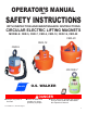
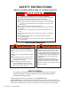
OPERATOR’S MANUAL AND SAFETY INSTRUCTIONS WITH INSPECTION AND MAINTENANCE INSTRUCTIONS CIRCULAR ELECTRIC LIFTING MAGNETS MODELS: CER-5, CER-7, CER-9, CER-12, CER-16, CER-20 CER-20 CER-12 CER-5 I/R CER-7 WALKER Always stay clear of the load. O.S. WALKER DANGER Never lift loads over people or in close proximity to people. Never attempt to operate this magnet until you have read and understand this Operator’s Manual. O.S. Walker Inc.
CONTENTS INTRODUCTION.................................................................................................................................... 2 SAFETY INSTRUCTIONS..................................................................................................................... 3 GENERAL SAFETY RULES.......................................................................................................................................3 UNSAFE LIFTING APPLICATIONS FOR YOUR MAGNET................
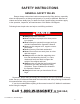
SAFETY INSTRUCTIONS GENERAL SAFETY RULES Danger always exists when loads are transported by lifting devices, especially when the equipment is not being used properly or is poorly maintained. Because accidents and severe bodily injury or death can result, special safety precautions apply to the operation, inspection, and maintenance of the Walker Lift Magnets. Following these simple rules can help to avoid lifting accidents: DANGER Always stay clear of the load.
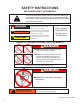
SAFETY INSTRUCTIONS RECOGNIZE SAFETY INFORMATION This is the safety alert symbol. When you see this symbol on your magnet or in this manual, be alert to the potential for personal injury. Follow recommended precautions and safe operating practices at all times. DANGER This indicates a situation in which a hazard is imminent and will result in a high probability of serious injury or death.
SAFETY INSTRUCTIONS WAYS TO AVOID A REDUCTION OF LIFTING CAPACITY DANGER To Avoid any Reduction of Lifting Capacity: The lifting surfaces of the magnet and the area of the load where the magnet will be located must be clean, smooth, flat and free of nicks and burrs. The full area of the magnet’s lifting surface must be in contact with the load. The load must be at least 1.0" (24.5 mm) thick for CER-5, 1.5” (38.1 mm) for CER7, 2” (51 mm) for models CER-9 through 12 and at least 2.
IMPORTANT FACTS FOR THE OPERATION OF LIFT MAGNETS LOAD CHARACTERISTICS OTHER THAN JUST WEIGHT MUST BE CONSIDERED IN ORDER TO DETERMINE THE LOAD THAT ANY MAGNET CAN LIFT. This statement is true for all lifting magnets because they all operate using the same fundamental laws of physics. Magnetic power is often pictured as lines of magnetic force flowing from north pole to south pole. Anything that limits the flow of these magnetic lines of force obviously reduces the magnet’s lifting capacity.
3. LOAD ALLOY Low carbon steels, such as SAE 1020 steel, are nearly as good conductors of magnetic lines of force as pure iron. However, many other alloys contain non-magnetic materials which reduce the ability of magnetic lines of force to flow into the load. An alloy such as SAE 300 series of stainless steel is almost as poor a conductor of magnetic lines of force as air.
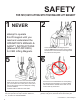
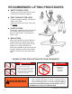
SAFETY FOR FAST, EASY LIFTING WITH YOUR WALKER LIFT MAGNET 1 NEVER attempt to operate this lift magnet until you read and understand the OPERATOR’S MANUAL & SAFETY INSTRUCTIONS (Manual #37-DD10505) for CER Lifting Magnets. 5 Check to be sure no one is near the load to be lifted. Inform others in the area that a lift is to begin. Lift the load 2 to 3 inches (50 to 75 mm) and then jar the load to insure that adequate holding power is available. ALWAYS STAY CLEAR OF THE LOAD.
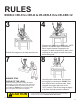
RULES MODELS: CER-5 thru CER-20 & I/R-CER-5 thru I/R-CER-12 3 4 Position the magnet so the load remains level. Energize the magnet by selecting the “LIFT” position. An indicator light will illuminate when electrical power is applied to the magnet. To obtain maximum lift, allow a few seconds for the magnet to reach full power before lifting load. 8 7 ALWAYS STAY CLEAR OF THE LOAD. Guide the load by pushing or pulling the edges. This keeps your entire body clear of the load at all times.
RECOMMENDED LIFTING PROCEDURES SAFETY HOOK LATCH Always use a safety hook latch on your crane hook to hold your magnets. STAY CLEAR OF THE LOAD Guide the load by pushing or pulling the edges of the load. Keep your entire body clear of the load at all times. PLATE LIFTING Position the magnet so that it is centered on the plate. Never lift any plate less than 1/4” (6mm) thick. (See Important Facts 2 & 4).
OPERATING INSTRUCTIONS MODELS: I/R-CER-5 thru I/R-CER-12 LOCAL PUSH BUTTON OPERATION: “LIFT MODE” To Energize the Magnet press and hold the “LIFT” push button until the green ring of the pushbutton illuminates. The magnet is now in the full “ON” position and will remain on until a release is selected. As a safety reminder the green lift led will begin to flash after 10 minuets in the “LIFT MODE” indicating you maybe exceeding the magnets rated duty cycle.
GUIDELINES FOR THE REDUCTION OF THE RATED LIFTING CAPACITY: CAUTION : Each Walker magnet model is rated for a different weight limit. Load characteristics will affect the lifting capacity of the magnets. The lifting guidelines for the various models are shown on the following pages. The Lifting Guidelines charts show the effect of air gap, load thickness, load length, and load width on lifting capacity. As the thickness of the load decreases, so does the rated lifting capacity of the magnet.
LIFTING GUIDELINES (PLATE) CER-5, CER-7, and CER-9 (plate) TYPE OF SURFACE CONDITION MAGNET MODELS LOAD THICKNESS CLEAN & SMOOTH Similar to a Flat (32 micro-inch RMS) Ground Surface .000” Max. Air Gap † Max. Load (lbs.) Max. Size (ft.) RUST OR SCALE Similar to a Flat Hot Rolled Steel Surface .010” Max. Air Gap † (.254mm) Max. Load (lbs.) Max. Size (ft.) IRREGULAR OR ROUGH Similar to a Flat Smooth Cut File .020” Max. Air Gap † (.508mm) Max. Load (lbs.) Max. Size (ft.
LIFTING GUIDELINES (PLATE) CER-12, CER-16, and CER-20 (plate) TYPE OF SURFACE CONDITION MAGNET MODELS LOAD THICKNESS CLEAN & SMOOTH Similar to a Flat (32 micro-inch RMS) Ground Surface .000” Max. Air Gap † Max. Load (lbs.) Max. Size (ft.) RUST OR SCALE Similar to a Flat Hot Rolled Steel Surface .010” Max. Air Gap † (.254mm) Max. Load (lbs.) Max. Size (ft.) IRREGULAR OR ROUGH Similar to a Flat Smooth Cut File .020” Max. Air Gap † (.508mm) Max. Load (lbs.) Max. Size (ft.
LOAD WEIGHT GUIDELINE To estimate the weight of a steel work piece, first determine the volume of the Load in cubic inches. Then multiply the volume (cubic inches) by the density of steel (.283) pounds per cubic inch. Load Weight (steel) = (volume) multiplied by (density) = (W x T x L) x (.283) Example: What is the weight of a 10” wide x 5” thick x 96” long piece of steel? Load Weight = (10 x 5 x 96) x (.283) = 1358 lbs DUTY CYCLE DO NOT EXCEED THE RATED 50% DUTY CYCLE OF THESE MAGNETS.
INSPECTION AND MAINTENANCE INSTRUCTIONS EVERY LIFT Keep the lifting surfaces of the magnet CLEAN, SMOOTH, FLAT, FREE OF RUST and any FOREIGN MATERIALS. Nicks and burrs on the lifting surfaces will reduce the lifting capacity. If burrs occur, they can be removed by filing them away. However, care must be taken to protect the neighboring lifting surfaces. Deep nicks may require regrinding of the entire lifting surfaces.
SPECIFICATION & PARTS LIST SPECIFICATIONS Model No. CER-5 CER-7 CER-9 CER-12 CER-16 CER-20 I/R-CER-5 I/R-CER-7 I/R-CER-9 I/R-CER-12 Power (Watts) 58 80 135 340 545 1050 58 80 135 340 Net Wt. (LBS) 23 43 94 142 320 560 30 50 101 142 H2 9.75” 11.25” 11.75” 13.63” 14.5” 15” 10.25” 11.75” 12.25” 13.63” Diameter “A” 5.12” 6.75” 9” 12” 16” 20” 5.12” 6.75” 9” 12” Figure No. 1 1 1 2 3 3 4 4 4 4 PERFORMANCE RATING ON SAE 1020 STEEL CER-5 0-600 lbs.
REPAIRS For repair of your lift magnet, contact O.S. Walker for you’re nearest Authorized Service Center TOLL FREE at 1-800-W-MAGNET. A return material authorization number will be issued along with the address of the nearest Authorized Service Center. Your magnet, after receipt by the Service Center will be inspected and a free estimate of repair charges will be provided. Authorization for repairs from magnet owners must be given to the O.S. Walker Service Center before repairs are made.
SPECIFICATION & PARTS LIST WARNING: IMPROPER WIRING CAN RESULT IN REDUCED HOLDING POWER. CER-5, 7 & 9 Replacement Parts List ITEM N0. PART DESCRIPTION 1 HOUSING 2 INDICATOR ASSY 3 PART NO.
SPECIFICATION & PARTS LIST WARNING: IMPROPER WIRING CAN RESULT IN REDUCED HOLDING POWER. CER-12 Replacement Parts List ITEM NO. PART DESCRIPTION PART NO.
SPECIFICATION & PARTS LIST WARNING: IMPROPER WIRING CAN RESULT IN REDUCED HOLDING POWER. CER-12 with PC Board Replacement Parts List ITEM NO. PART DESCRIPTION PART NO.
WARNING: IMPROPER WIRING CAN RESULT IN REDUCED HOLDING POWER. I/R-CER-5 THRU 12 Replacement Parts List ITEM NO. PART DESCRIPTION PART NO.
SPECIFICATION & PARTS LIST WARNING: IMPROPER WIRING CAN RESULT IN REDUCED HOLDING POWER. CER-16 & 20 Replacement Parts List ITEM NO. PART DESCRIPTION PART NO.
ALWAYS STAY CLEAR OF THE LOAD Guide the load by pushing or pulling the edges. This keeps your entire body clear of the load at all times. DO NOT guide the load by pushing or pulling the magnet. NEVER get in a position where you could get hit with the load if it is dropped. FOR FAST RESPONSE, CALL 1-800-W-MAGNET O.S.