W60C73BL, W60C73MB, W60C73CH ASSEMBLY INSTRUCTIONS For our most up-to-date instructions, to request missing, lost, or broken parts, or for any other Customer Service issues, please visit our website at www.walkeredison.com or call us at 877-207-5906.
General Assembly Guidelines I. Ensure that all parts are available before beginning assembly. II. Follow each step carefully to ensure proper assembly of this product. III. The four main types of hardware used to construct this TV console are: wood dowels, cam and bolt, hex-head bolts, and screws. IV. Two people are recommended for ease in assembly of this product. V. Power tools should not be used to assemble this product. VI. To attach wood dowels, place provided glue in the holes before inserting dowel.
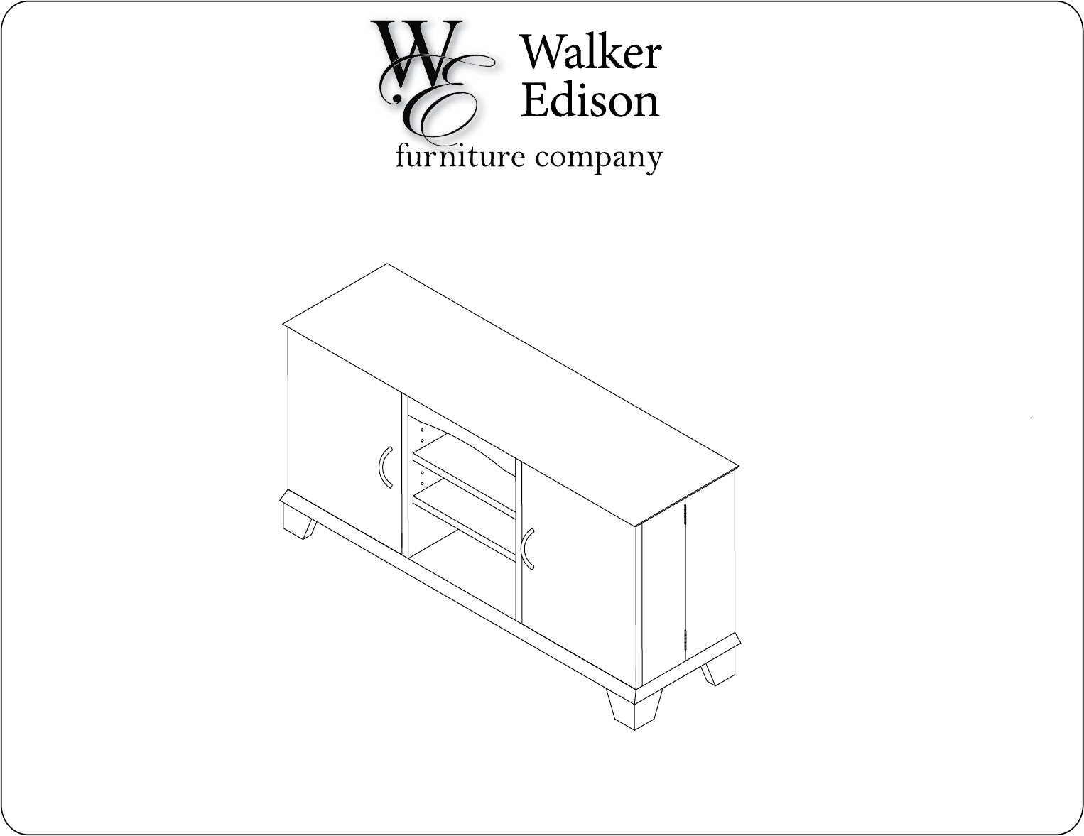
W60C73BL, W60C73MB, W60C73CH Parts List 3
W60C73BL, W60C73MB, W60C73CH Hardware Parts List * The hardware quantities listed are required for proper assembly. Some extra hardware may have also been included.
B 1. 2. A J K 18 D B P C 19 13 17 13 N B A 15 D K B J C 13 P 14 13 B 16 N A Assemble door frames using dowels (C) and cam bolts (B). Tighten cam locks (A) using a screwdriver as shown in the diagram. Build door faces by attaching cam bolts (B) and fastening plates (J). Attach door handles (N) to the front of doors.
3. 4. A 18 A D C 17 D 7 19 6 C 15 A 14 5 D 16 C Insert dowels (C) into door faces. Attach the door faces to the door frames. Tighten cam locks (A) using a screw driver as shown. Set door assembly aside for later use. 6 Assemble the center shelf frame section by inserting dowels (C) and attaching the pieces as shown in the diagram.
5. Finished sides face out B 4 B . 9 C A 6 D 5 . 9 B C A 3 D Assemble and attach the side shelf frames to the center frame section using dowels (C), cam locks (A) and cam bolts (B). Tighten cam locks (A) using a screwdriver as shown in the diagram.
6. Attach cam bolts (B) and door stops (G) to the stand top as shown. 7. Insert dowels (C) and cam locks (A) into the stand top. Attach the frame to the stand top (2 people recommended). Tighten cam locks (A) using a screwdriver as shown in diagram.
8. 9. E F 11 2 10 11 Attach the base to the frame assembly with hex screws (E). Tighten using the provided hex wrench (F). Slide the back panel sections (10 & 11) into the stand frame.
. 11. R D Q R S C Insert dowels (C) into stand base. Attach corner legs (S) to dowels. Attach middle legs (Q) into predrilled starter holes with screws (R). Tighten with a screwdriver. 10 Attach the hinges (L) to the assembled doors using screws (M).
12. Attach the door hinges to the stand frame using screws (M). Align edge of hinges with edge of frame. Tighten with a screwdriver. You may need to loosen screws, adjust placement of hinges and re-tighten for proper alignment of doors on frame.
14. 13. 8 8 I Insert shelf support pins (I) to frame at desired height and carefully place shelves as shown in the diagram. Small plastic wedges (R) are optional and can be used to tighten the fit of the back panels against the framework. Secure wedges to back panels using screw (S).