
Technical data

Counter Module 750-404 10
:$*2⇓,2⇓6<67(0
Functional description
The counter module acquires the time between one or more rising edges of the CLOCK
input signal and calculates the frequency of the applied signal.
The calculation and process imag e update are initiated every 1
st
, every 4
th
or every 16
th
rising edge depending on the integration time selected via the CONTROL byte. The first
detection of a rising edge starts the cy clic period measurement and cannot provide a
valid frequency value. I n this case the module will send 0x FFFFFFFF
H
for input
information. The same input value is returned when a static hig h or static low signal is
applied to the CLOCK input.
If there are no sig nal changes seen at the CL OCK input, the module can be forced to
update the process imag e after defined parameterizable time spans. I n this state the
module will send the non valid value 0xFFFFFFFF
H
too.
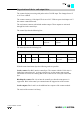
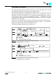
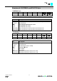
The following figures illustrate a process data cycle.
7
I
FXUUHQWSHULRG
7
0D[LPXPGDWDKROGWLPHSDUDPHWHUL]DEOH
,QSXW'DWD
''
Figure 2: Timing diagram for process data update sequence
(integration time = 1 period)
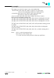
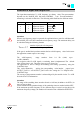
7
I
FXUUHQWSHULRG
7
0D[LPXPGDWDKROGWLPHSDUDPHWHUL]DEOH
,QSXW'DWD''
Figure 3: Timing diagram for process data update sequence
(integration time = 4 periods)