
Technical data


Fieldbus Controller 750-841 • 87
Programming the PFC with WAGO-I/O-PRO CAA
WAGO-I/O-SYSTEM 750
ETHERNET TCP/IP
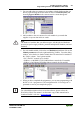
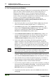
3. You can add to the tree structure in accordance with the hardware that you
have by right-clicking the mouse button on the text Controller[FIX] and
choosing Append Module in the context-sensitive menu that appears.
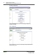
4. Add a module to the tree structure for each module in your node that
supplies or expects data in bits or words.
Note
The number of modules that you add must agree with the physical hardware
present (except for supply modules, potential multiplication modules, and end
modules).
5. For each module added, click on the text Module[var] and then click on the
Module parameters tab in the right-hand dialog window. From the dialog
window, select the device (Index 10000) that will control the I/O module in
the "Value" column. Your options include:
- PLC (The PFC controls its I/O locally)
- fieldbus 1 (A MODBUS TCP Fieldbus Master controls the I/O module)
- fieldbus 2 (An Ethernet IP Fieldbus Master controls the I/O module)
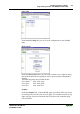
6. When you have completed the assignments, you can start programming with
the IEC 61131-3 program tool. The configuration file “EA-config.xml” is
generated as soon as you compile the project.
More information
For a detailed description on how to use the software, please refer to the
WAGO-I/O-PRO CAA manual. An electronic copy of this manual can be
found on WAGO’s web site: www.wago.com