
Technical data


82 • Fieldbus Controller 750-841
Starting up an ETHERNET TCP/IP fieldbus node
WAGO-I/O-SYSTEM 750
ETHERNET TCP/IP
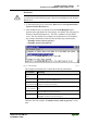
3. Cursor to the text line: "node1:ht=1:ha=0030DE000100:ip=10.1.254.100"
and replace the 12 character hardware address, which is entered after “ha=”,
with your PFC’s MAC-ID.
4. If you want to give your fieldbus node a different name, replace the name
"node1" with your new name.
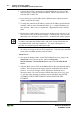
5. To assign the controller an IP address, replace the IP address specified in the
example, which is entered immediately after “ip=”, with the IP address you
have selected. Make sure you separate the 3 digit numbers with a decimal
point.
6. Because the second example is not necessary in this exercise, insert a “#” in
front of the text line of the second example: "# hamburg:hat=1:ha=003 0DE
0002 00:ip=10.1.254.200:T3=0A.01.FE.01", so that this line will be ignored.
Note
To address more than one fieldbus nodes, add a line of setup information for
each additional PFC in the file bootptab.txt . Use steps 2 through 4 as a
guideline for configuring each additional module.
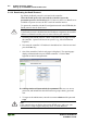
7. Save the new settings in the text file "bootptab.txt". To do this, go to the File
menu, menu item Save, and then close the editor.
BootP Server
8. Now open the dialog window for the WAGO BootP server by going to the
Start menu on your screen surface, menu item Program /
WAGO Software / WAGO BootP Server and click on WAGO BootP
Server.
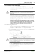
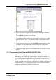
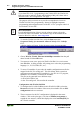
9. After the editor closes, Click on the Start button in the opened BootP dialog
window. This will activate the inquiry/response mechanism of the BootP
protocol. A series of messages will be displayed in the BootP server
message window. The error messages indicate that some services (e.g. port
67, port 68) in the operating system have not been defined. DO NOT BE
ALARMED, THIS IS THE CORRECT OPERATION FOR THIS
EXAMPLE.
Fig. 3-12 Dialog Window of the WAGO BootP Server with Messages P012909d