
Technical data


68 • Fieldbus Controller 750-841
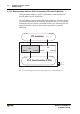
Data Exchange
WAGO-I/O-SYSTEM 750
ETHERNET TCP/IP
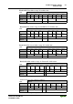
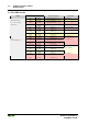
Overview of the IEC 61131-3 address ranges:
Address range MODBUS
Access
SPS
Access
Description
phys. Inputs read read Physical Inputs (%IW0 ... %IW255 and
%IW512 ... %IW1275)
phys. Outputs read/write read/write Physical Outputs (%QW0 ... %QW255 and
%QW512 ... %QW1275)
MODBUS/TCP
PFC IN variables
read/write read Volatile SPS Input variables (%IW256 ... %IW511)
MODBUS/TCP
PFC OUT variables
read read/write Volatile SPS Output variables (%QW256 ... %QW511)
Ethernet/IP
PFC IN variables
read/write read Volatile SPS Input variables (%IW1276 ... %IW1531)
Ethernet/IP
PFC OUT variables
read read/write Volatile SPS Output variables (%QW1276 ... %QW1531)
Configuration register read/write --- see Chapter „Ethernet“
Firmware register read --- see Chapter „Ethernet“
Flags/RETAIN
variables
read/write read/write Remanent memory (%MW0 ... %MW12288)
Table 3.7: Overview IEC 61131-3 Address ran
g
es
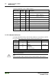
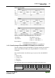
3.1.5.2.3 Absolute Addresses
Accessing individual memory cells (absolute addresses) in accordance with IEC
61131-3 is made using special character defined in the table below:
Position Character Designation Comments
1 % Starts absolute address
2 I Input
Q Output
MFlag
3 X* Single bit Data width
BByte (8 Bits)
W Word (16 Bits)
D Double word (32 Bits)
4 Address
e. g. word wise: %QW27 (28. Word), bit wise: %IX1.9 (10. Bit in Word 2)
* The character ‘X’ for bits can be deleted
Table 3.8: Absolute Addresses
Note
Enter the absolute address character strings without blanks (white spaces)!