
Technical data


66 • Fieldbus Controller 750-841
Data Exchange
WAGO-I/O-SYSTEM 750
ETHERNET TCP/IP
3.1.5.2 Addressing
3.1.5.2.1 Addressing the I/O Modules
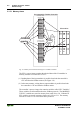
The arrangement of the I/O modules in a node is flexible and up to the user.
Although, the user must verify that the power jumper contacts from one I/O
module to the next are compatible and at the same voltage level.
When the controller addresses I/O modules, data of complex modules (modules
occupying 1 or more bytes) are mapped first. They are mapped in the order of
their physical position after the controller. As such, they occupy the addresses
beginning with word 0. Following this, the digital modules are grouped in the
form of words (16 bits per word). They are also arranged by their physical
order. When the number of digital I/O’s exceeds 16 bits, the controller
automatically starts another word.
Note
For detailed information on the number of input and output bits/bytes of a
specific module, please refer to the modules manual.
Note
Changing the physical layout of a node will result in a new structure of the
process image. Also, the addresses of the process data will change. When
adding or removing modules, the process data must be verified.
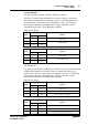
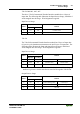
Data width ≥ 1 Word / channel Data width = 1 Bit / channel
Analog input modules Digital input modules
Analog output modules Digital output modules
Input modules for thermal elements Digital output modules with diagnosis (2 Bit / channel)
Input modules for resistance sensors Power supply modules with fuse holder / diagnosis
Pulse width output modules Solid State power relay
Interface module Relay output modules
Up/down counter
I/O modules for angle and path measurement
Table 3.1: I/O Module Data Width
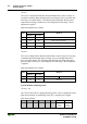
3.1.5.2.2 Address Range
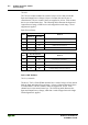
Partition of Address ranges for the word-wise addressing acc. to IEC 61131-3 :
Word Data
0-255 physical I/O modules
256-511 MODBUS/TCP PFC variables
512-1275 remaining physical I/O modules
1276-1531 Ethernet/IP PFC variables
1532-..... reserved for PFC variables of future protocols