
Technical data


Fieldbus Controller 750-841 • 65
Data Exchange
WAGO-I/O-SYSTEM 750
ETHERNET TCP/IP
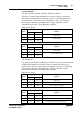
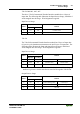
(3) The PFC input variables are written into the input memory space from the
fieldbus master and can be read by the controller’s CPU for further
processing.
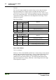
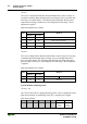
(4) The variables processed by the controller’s CPU , via an IEC 61131-3
application program, can be written to the PFC Variables and then read by
the fieldbus master.
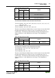
In addition, with the MODBUS TCP/IP protocol, all output data has a
mirrored image in memory with the address offset 0x0200 or 0x1000. This
permits reading back output values after they are written by adding 0x0200 or
0x1000 to the MODBUS address.
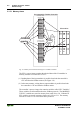
In addition, the controller offers other memory spaces which partly cannot be
accessed from the fieldbus master:
RAM
The RAM memory is used to create variables not required for
communication with the interfaces but for internal processing,
such as for instance computation of results.
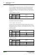
The remanent memory is non volatile memory, i.e. all values are
retained following a voltage failure. The memory management is
automatic. In this 24 kByte sized memory area (word 0 ...
12288), flags for the IEC 61131-3 program are filed together
with variables without memory space addressing or variables
which are explicitly defined with "var retain".
Remanent
Memory
(Retain)
Note
The automatic memory management can cause a data
overlap. For this reason, we recommend not to use a
mix of flags and retain variables.
Code-
Memory
The IEC 61131-3 program is filed in the code memory. The code
memory is a flash ROM. Once the supply voltage is applied, the
program is transmitted from the flash to the RAM memory. After
a successful start-up, the PFC cycle starts when the operating
mode switch is turned to its upper position or by a start
command from WAGO-I/O-PRO CAA.