
Technical data


64 • Fieldbus Controller 750-841
Data Exchange
WAGO-I/O-SYSTEM 750
ETHERNET TCP/IP
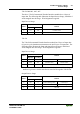
3.1.5.1 Memory Areas
12
2
4
4
CPU
I
O
11
1
3
1
Programmable Fieldbus Controller
memory area
for input data
input
modules
IEC 61131-
program
memory area
for output data
fieldbus
master
I/O modules
word 1276
word 1531
word 0
word 255
word 256
MODBUS
PFC-OUT-
variables
word 511
word 1276
Ethernet IP
PFC-OUT-
variables
word 1531
word 1275
word 512
word 0
word 255
word 256
MODBUS
PFC-IN-
variables
word 511
word 512
word 1275
Ethernet IP
PFC-IN-
variables
input
modules
output
modules
output
modules
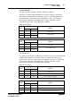
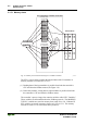
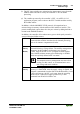
Fig. 3-8: Memory Areas and Data Exchange for a Fieldbus Controller g015038e
The PFC‘s process image contains the physical data of the I/O modules in
memory words 0 to 255 and 512 to 1275.
(1) Reading data of the input modules is possible from both the controller’s
CPU and from the fieldbus master (See Figure 3-8).
(2) In the same manner, writing data to output modules is possible from both
the controller’s CPU and from the fieldbus master.
The controller’s process image also contains variables called “PFC Variables”.
These variables are allocated based on the fieldbus protocols. The MODBUS
TCP PFC variables are stored in memory from word 256 to 511. Ethernet IP
PFC variables are stored in memory from word 1276 to 1531. The memory
area above word 1531 is reserved for future protocols.