
Technical data


62 • Fieldbus Controller 750-841
Process Image
WAGO-I/O-SYSTEM 750
ETHERNET TCP/IP
750-637
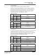
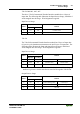
The 750-637 Incremental Encoder Interface Module has a total of 6 bytes of
user data in both the Input and Output Process Image (4 bytes of encoder data
and 2 bytes of control/status). The following table illustrates the Input and
Output Process Image, which has 4 words mapped into each image. Word
alignment is applied.
Input and Output Process Image
Byte Destination
Offset
High Byte Low Byte
Remark
0 - C0/S0 Control/Status byte of Channel 1
1 D1 D0 Data Value of Channel 1
2 - C1/S1 Control/Status byte of Channel 2
3 D1 D0 Data Value of Channel 2
750-635
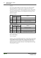
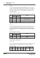
The 750-635 Digital Pulse Interface module has a total of 4 bytes of user data
in both the Input and Output Process Image (3 bytes of module data and 2
bytes of control/status). The following table illustrates the Input and Output
Process Image, which has 2 words mapped into each image. Word alignment
is applied.
Input and Output Process Image
Byte Destination
Offset
High Byte Low Byte
Remark
0 D0 C0/S0 Data byte Control/Status byte
1 D2 D1 Data bytes
System Modules with Diagnostics:
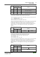
750-610, -611
The 750-610 and 750-611 Supply Modules provide 2 bits of diagnostics in the
Input Process Image for monitoring of the PFC’s internal power supply.
Input Process Image
Bit 7 Bit 6 Bit 5 Bit 4 Bit 3 Bit 2 Bit 1 Bit 0
Diagnostic
bit S 2
Fuse
Diagnostic
bit S 1
Voltage