
Technical data


Fieldbus Controller 750-841 • 61
Process Image
WAGO-I/O-SYSTEM 750
ETHERNET TCP/IP
750-631/000-003, -005, -007
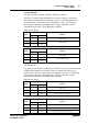
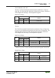
The above 750-631 Incremental Encoder Interface modules have 4 bytes of
input data. The following table illustrates the Input Process Image, which has 2
words mapped into the image. Word alignment is applied.
Input Process Image
Byte Destination
Offset
High Byte Low Byte
Remark
0 D1 D0 Counter Value
1 D3 D2 Latch word
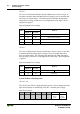
750-634
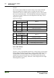
The 750-634 Incremental Encoder Interface module has 5 bytes of input data
(6 bytes in cycle duration measurement mode) and 3 bytes of output data. The
following tables illustrate the Input and Output Process Image, which has 3
words mapped into each image. Word alignment is applied.
Input Process Image
Byte Destination
Offset
High Byte Low Byte
Remark
0 D0 S Counter Value Status byte
1(D2)*
)
D1 (Periodic time) Counter Value
2 D4 D3 Latch word
*
)
If cycle duration measurement mode is enabled in the control byte, the cycle
duration is given as a 24-bit value that is stored in D2 together with D3/D4.
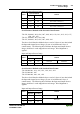
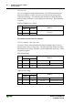
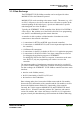
Output Process Image
Byte Destination
Offset
High Byte Low Byte
Remark
0 D0 C Counter Setting Value Control byte
1 - D1 not used Counter Setting Value
2- - not used