
Technical data


60 • Fieldbus Controller 750-841
Process Image
WAGO-I/O-SYSTEM 750
ETHERNET TCP/IP
750-654, -630
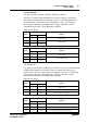
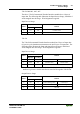
The 750-654 Data Exchange module and the 750-630 Incremental Encoder
Interface module have a total of 4 bytes of user data in both the Input and
Output Process Image. The following table illustrates the Input and Output
Process Image, which has 2 words mapped into each image. Word alignment
is applied.
Input and Output Process Image
Byte Destination
Offset
High Byte Low Byte
Remark
0D1 D0
1D3 D2
Data bytes
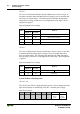
Incremental Encoder Interface Modules:
750-631, /000-001, -004, -006, -008
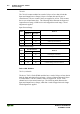
The above 750-631 Incremental Encoder Interface modules have 5 bytes of
input data and 3 bytes of output data. The following tables illustrate the Input
and Output Process Image, which has 3 words mapped into each image. Word
alignment is applied.
Input Process Image
Byte Destination
Offset
High Byte Low Byte
Remark
0 D0 S Counter Value Status byte
1 - D1 not used Counter Value
2 D4 D3 Latch word
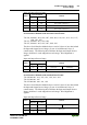
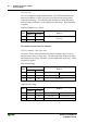
Output Process Image
Byte Destination
Offset
High Byte Low Byte
Remark
0 D0 C Counter Setting Value Control byte
1 - D1 not used Counter Setting Value
2- - not used