
Technical data


56 • Fieldbus Controller 750-841
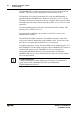
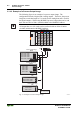
Process Image
WAGO-I/O-SYSTEM 750
ETHERNET TCP/IP
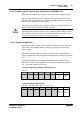
3.1.4.3.4 Analog Output Modules
The hardware of an analog output module has 16 bits of analog output data per
channel and 8 status bits. However, the Ethernet controller does not have
access to the 8 status bits. Therefore, the Ethernet controller can only supply
the 16 bits of analog data per channel, which is grouped as words and mapped
in Intel format in the Output Process Image.
When digital output modules are also present in the node, the analog output
data is always mapped into the Output Process Image in front of the digital
data.
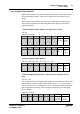
2 Channel Analog Output Modules
750-550, -552, -554, -556, -560, -585
Byte Destination
Offset
High Byte Low Byte
Remark
0 D1 D0 Output Value Channel 1
1 D3 D2 Output Value Channel 2
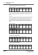
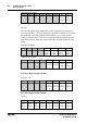
4 Channel Analog Output Modules
750-557, -559
Byte Destination
Offset
High Byte Low Byte
Remark
0 D1 D0 Output Value Channel 1
1 D3 D2 Output Value Channel 2
2 D5 D4 Output Value Channel 3
3 D7 D6 Output Value Channel 4
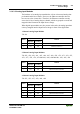
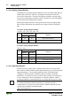
3.1.4.3.5 Specialty Modules
WAGO has a host of Specialty I/O modules that perform various functions.
Most of these modules contain control and status memory, as well as input and
output data memory. These memory addresses allow for bi-directional
exchange of data between the controller and the I/O module. With this
architecture, it is possible to preset a counter value by means of a control byte
or use a status byte to detect a undershoot or overshoot condition. When a
specialty module has a control/status byte, it is always the low byte of a word.
Further information
For detailed information about the structure of a particular module’s
control/status byte, please refer to that module’s manual. Manuals for each
module can be found on the Internet under:
http://www.wago.com.